Battery unit and power supply device

Inactive Publication Date: 2013-01-31
NEC ENERGY DEVICES LTD
View PDF3 Cites 7 Cited by
  • Summary
  • Abstract
  • Description
  • Claims
  • Application Information

AI Technical Summary

Benefits of technology

[0013]According to the present invention, maintenance of the la

Problems solved by technology

However, clean energy has a problem in which there is a amount of fluctuation in the output depending upon the situations.
For example, energy that is generated from solar power is acquired when the sun is out but cannot be acquired at night when the sun has set.
However, the lead storage battery is generally large, and has a drawback of low energy

Method used


Image

  • Battery unit and power supply device
  • Battery unit and power supply device
  • Battery unit and power supply device

Examples


Example

First Embodiment

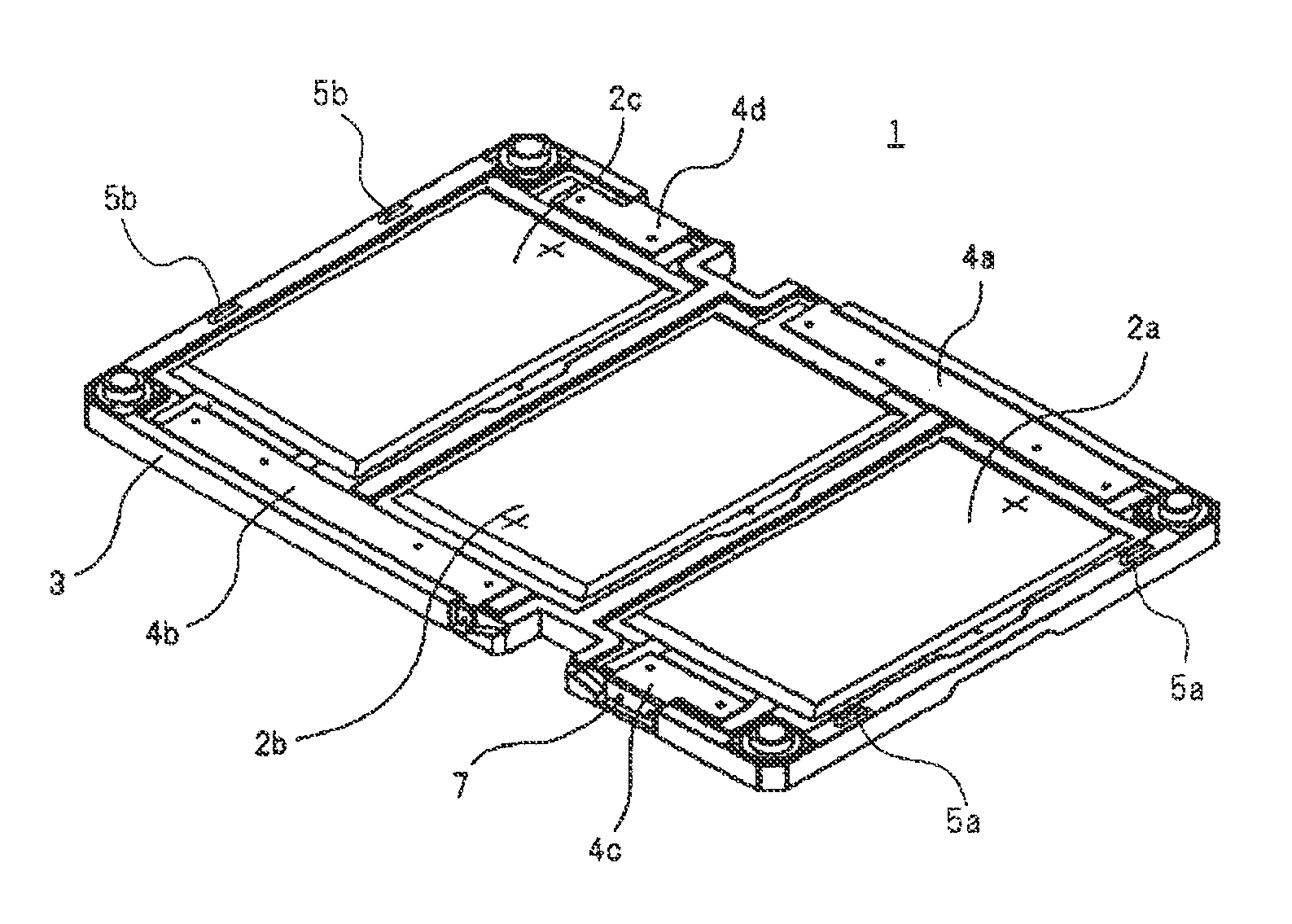
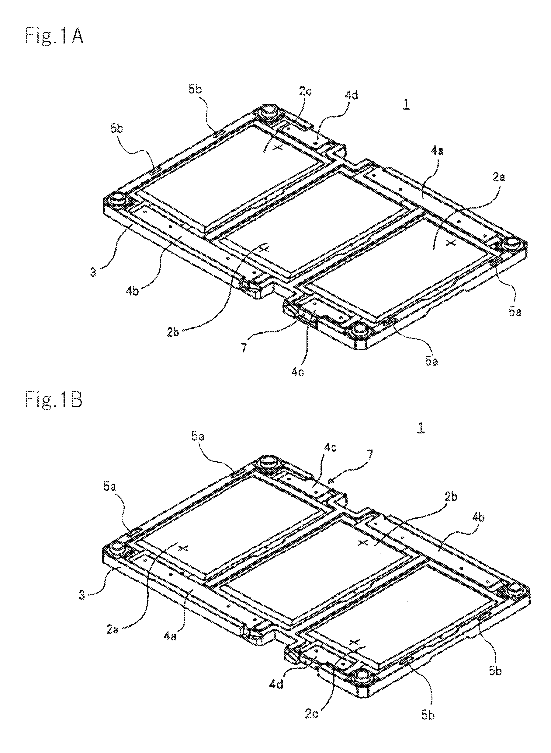
[0033]FIGS. 1A and 1B are perspective views showing battery unit 1 according to a first embodiment when seen from above. FIG. 1B shows battery unit 1 from a side of a horizontal direction opposite that shown in FIG. 1A.

[0034]Battery unit 1 according to this embodiment includes three flat-plate laminate batteries 2a to 2c, and tray 3 to which laminate batteries 2a to 2c are attached.

[0035]In this embodiment, lithium ion secondary batteries are used as laminate batteries 2a to 2c. However, the laminate batteries are not limited to the lithium ion secondary batteries. Other laminate batteries such as nickel hydride batteries can be used.

[0036]Three laminate batteries 2a to 2c are arrayed in tray 3 so that positive electrodes and negative electrodes can be opposite each other. In other words, the positive electrode and the negative electrode of laminate batteries 1a and 1c are in the same direction, while the positive electrode and the negative electrode of laminate bat...

Example

Second Embodiment

[0072]FIG. 9 is a side sectional view showing power supply device 20 according to a second embodiment. Power supply device 20 is configured by stacking four battery units 1c. Power supply device 20 according to the second embodiment is similar in configuration to power supply device 10 according to the first embodiment except for the following components.

[0073]Tray 13 of battery unit 1c according to this embodiment includes partition walls to respectively surround the outer peripheral portions of laminate batteries 2a to 2c. Battery units 1c are stacked, and tray 13 and the lower surface of tray 13 adjacent to the upper surface of this tray 13 form individual chambers to respectively cover laminate batteries 1a to 1c. Only uppermost battery unit 1c does not include tray 13 adjacent to the upper surface of tray 13. Cap 14 made of the same material as that of tray 13 is disposed on uppermost battery unit 1c. Cap 14 can be substituted for control board 11 shown in FIG...

Example

Third Embodiment

[0078]FIG. 11 is a perspective view showing power supply device 30 according to a third embodiment. Power supply device 30 is configured by stacking a plurality of battery units 1e. Power supply device 30 according to this embodiment is similar in configuration to power supply device 10 according to the first embodiment except for the components described below. For convenience, tray 23 of each battery unit 1e is indicated by a broken line.

[0079]In each battery unit 1e of power supply device 30 according to this embodiment, the positive electrodes and the negative electrodes of laminate batteries 22a to 22c are pulled out in the same direction. In power supply device 30, the negative electrode of laminate battery 22a and the positive electrode of laminate battery 22b are electrically connected to each other via bus bar 24a, and the negative electrode of laminate battery 22b and the positive electrode of laminate battery 22c are electrically connected to each other v...


PUM


Abstract

Disclosed is a battery unit that includes: a plurality of laminate batteries (32) electrically connected with each other; and tray (33) on which the plurality of laminate batteries (32) is mounted and which is stackable on another tray (33) on which another plurality of laminate batteries (32) is mounted. On the respective outer peripheral portions of the plurality of laminate batteries (32), there are formed gas discharge sections (35) that respectively release pressures generated in the plurality of laminate batteries (32) to the outside. The plurality of laminate batteries (32) is disposed such that gas discharge sections (35) are adjacent to the outer peripheral portion of tray (33).

Description

TECHNICAL FIELD [0001]The present invention relates to a battery unit that includes a plurality of laminate batteries electrically connected with each other, and a power supply device that includes the battery unit.BACKGROUND ART [0002]In recent years, in view of environmental problems, attention has been focused on clean energy acquired from wind power generation or solar power generation, which can be put to household use of a detached house or industrial use such as a transport device or a construction device. However, clean energy has a problem in which there is a amount of fluctuation in the output depending upon the situations. For example, energy that is generated from solar power is acquired when the sun is out but cannot be acquired at night when the sun has set.[0003]To stabilize the output of clean energy, a technology for temporarily storing the clean energy is used. For example, energy from sunlight stored in a battery can be used even at night after the sun has set. As...

Claims


Application Information

Patent Timeline
IPC IPC(8): H01M2/10H01M2/12H01M50/211
CPCH01M2/1241H01M2/1077Y02E60/10H01M50/3425H01M50/211
Inventor SUZUKI, TORU
Owner NEC ENERGY DEVICES LTD
Why Eureka
Try Eureka