Bone staple, instrument and method of use and manufacturing

a technology of bone staples and instruments, applied in the field of bone staples, to achieve the effect of simple, reliable and low cos

a technology of bone staples and instruments, applied in the field of bone staples, to achieve the effect of simple, reliable and low cos

US20130030438A1Active Publication Date: 2013-01-31FOX WILLIAM CASEY

Image

  • Bone staple, instrument and method of use and manufacturing
  • Bone staple, instrument and method of use and manufacturing
  • Bone staple, instrument and method of use and manufacturing

Examples


Embodiment Construction

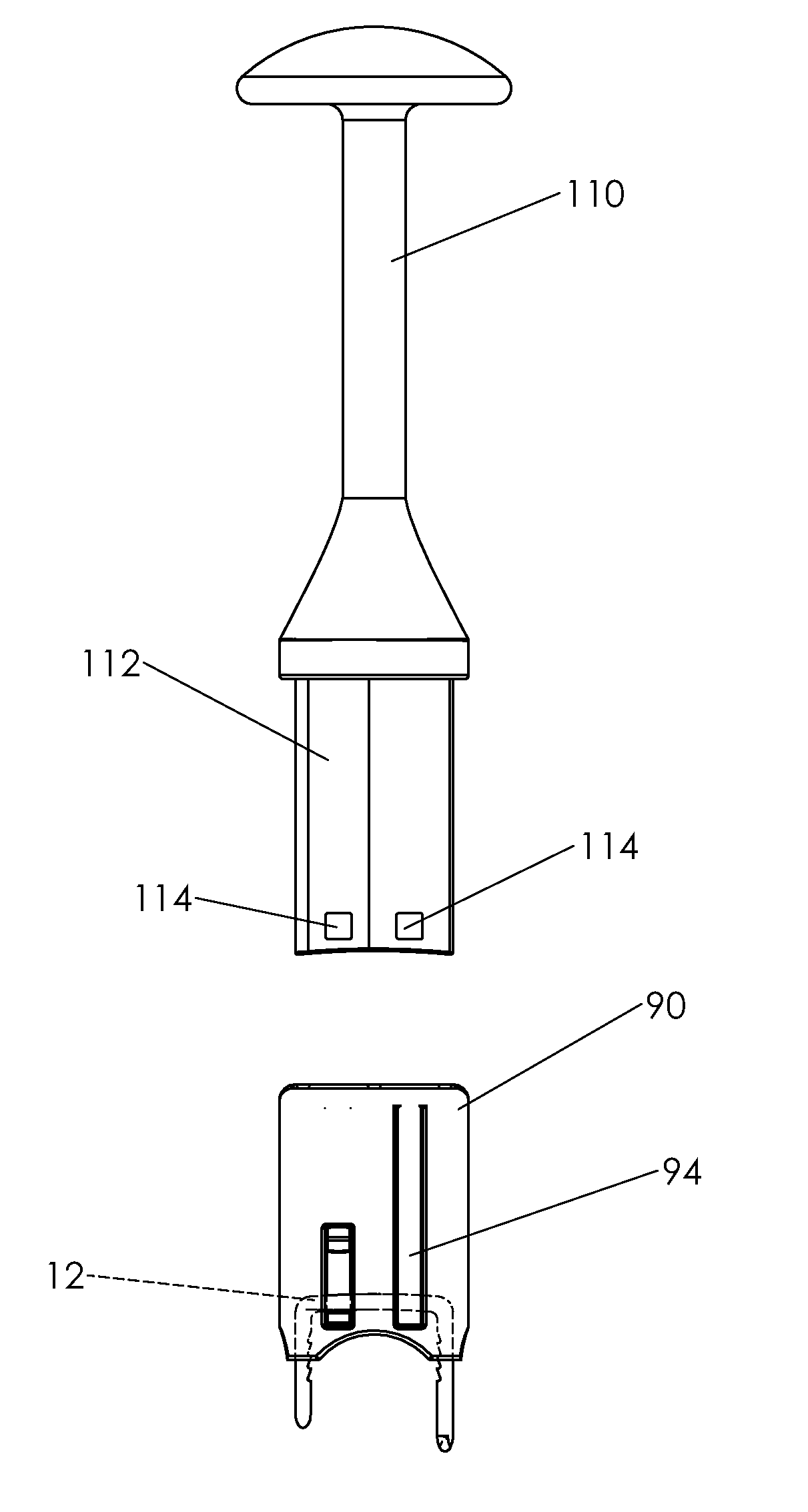
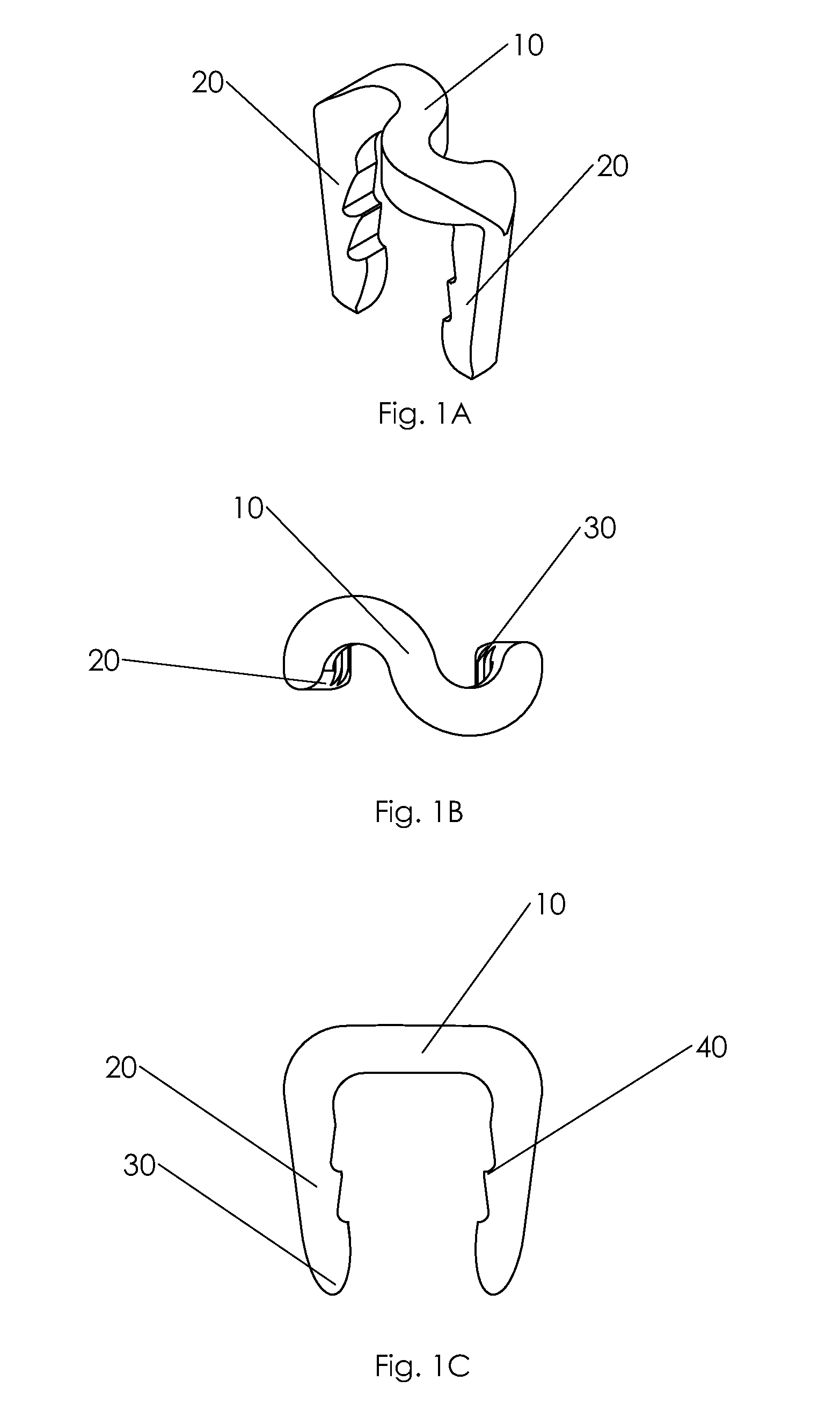
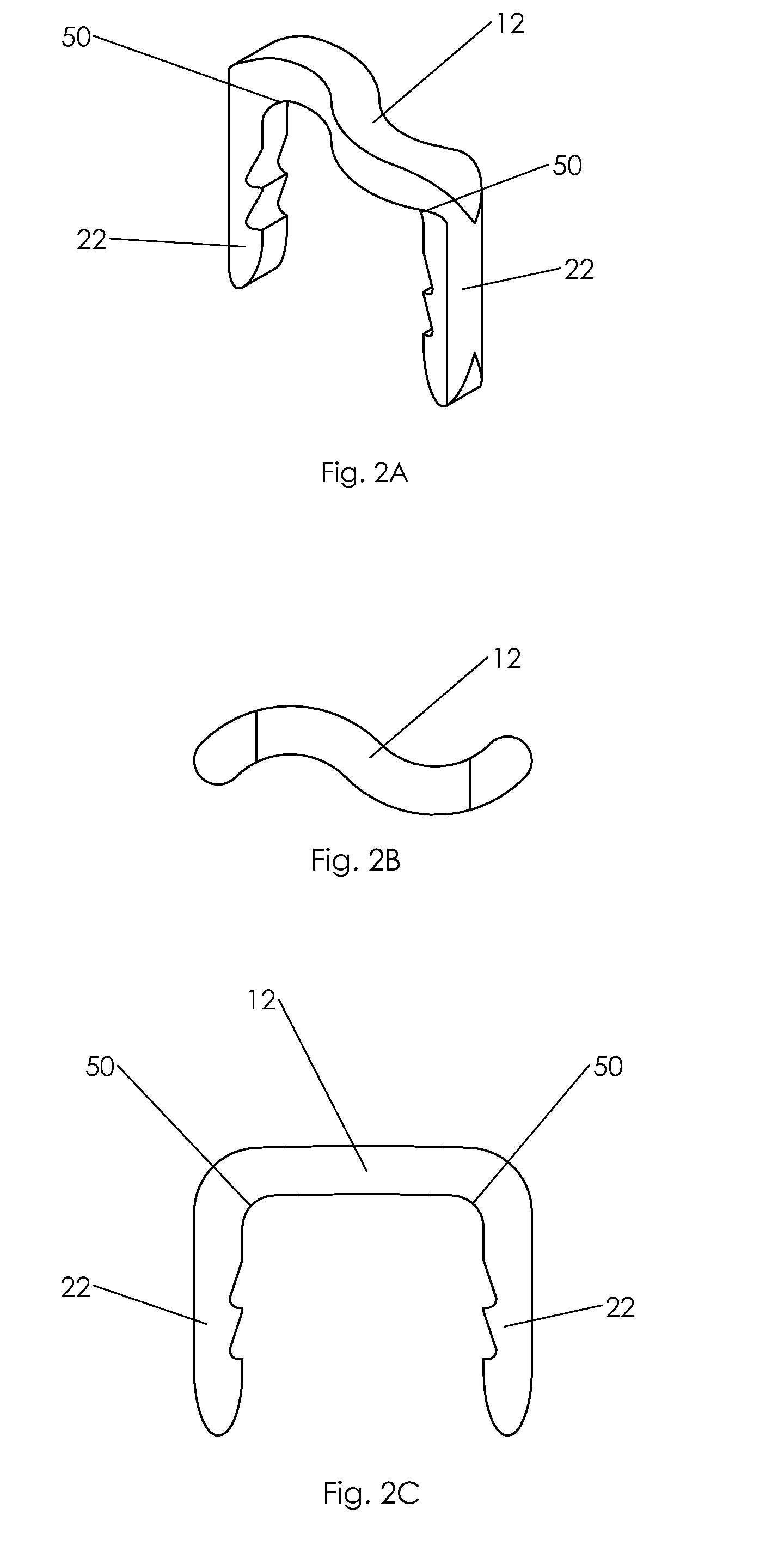
[0232]The embodiments of the subject invention consist of a staple with a plurality of legs commonly in a U- or table shaped configuration where the U-shaped has two legs and the table-shaped has 4 legs. All staple styles independent of the number of legs have a bridge that joins the plurality of legs.

[0233]As discussed and described herein, embodiments of the present inventions include staples and methods of use including staples in which the staples are able to move between two shapes, with, generally, one shape being a “parallel” shape and the other shape being a “non-parallel” shape. A staple has a “parallel” shape when the legs of the staple are in a substantially parallel orientation, as opposed to a convergent orientation or a divergent orientation. A staple has a “non-parallel” shape when the legs of the staple are not in a substantially parallel orientation, i.e., the staple is in a convergent orientation or a divergent orientation.

[0234]When a staple is a “convergent stapl...


PUM

PropertyMeasurementUnit
transition temperatureaaaaaaaaaa
temperaturesaaaaaaaaaa

Abstract

A new shape changing staple and instrument for the fixation of structures to include bone tissue and industrial materials. This new staple stores elastic mechanical energy to exert force on fixated structures to enhance their security and in bone affect its healing response. This staple once placed changes shape in response to geometric changes in the materials structure, including healing bone tissue. The staple is advanced over prior staples due to its: 1) method of operation, 2) high strength, 3) method of insertion, 4) compressive force temperature independence, 5) energy storing staple retention and delivery system, 6) compatibility with reusable or single use product configuration, 7) efficient and cost effective manufacturing methods, and 8) reduction in the steps required to place the device. In addition to the staple's industrial application an embodiment for use in the fixation of the musculoskeletal system is shown with staple, cartridge, and extrusion handle.

Description

TECHNICAL FIELD[0001]This application relates to staples used for fixation of bone and soft tissue of the musculoskeletal system and the methods for their use and more specifically to staples that are caused to change shape through their metallurgic properties and their interaction with mechanical instruments to pull together and compress bone.BACKGROUND[0002]Bone staples have been in clinical use for decades. These important bone fixation devices have evolved from rigid stainless steel or cobalt-chromium U-shaped implants to staples that could be manipulated to compress two adjacent bone segments.[0003]The early rigid staples were commonly hammered into bone where the more modern devices are implanted in drilled holes and use heat or mechanical means to cause the staple to change shape and pull together and in some designs compress the bony segments. Bone staple technology used to pull bone together includes: 1) staples that are bent by an instrument: BENDABLE STAPLES, 2) heat sens...

Claims


Application Information

Patent Timeline
31 Jan 2013
Publication
US20130030438A1
IPC
A61B17/84; B23P17/00; B21G7/02
CPC
A61B17/0642; A61B17/0682; A61B2017/00526; Y10T29/49874; A61B2017/0645; A61B2017/0688; A61B17/105; A61B2017/00867
Inventors
FOX, WILLIAM CASEY