
Motherboard alarm system test circuit

a test circuit and alarm system technology, applied in the field of motherboard alarm systems, can solve problems such as incorrect operation, motherboard alarm system abnormal state, memory fault,

Inactive Publication Date: 2013-01-31
HONG FU JIN PRECISION IND (SHENZHEN) CO LTD +1
View PDF0 Cites 21 Cited by
  • Summary
  • Abstract
  • Description
  • Claims
  • Application Information

AI Technical Summary

Benefits of technology

The present patent relates to a motherboard alarm system test circuit that can overcome the limitations of current testing methods. The test circuit includes an infrared emitter and a circuit board with a memory and edge connectors. The infrared emitter emits infrared light when activated, and the circuit board has a memory slot with metal sheets connected to the memory via edge connectors. The test circuit is designed to set the memory at a low level voltage to test for faults, and can output an alarm if a fault is detected. The test circuit simplifies the testing process and prevents incorrect operation.

Problems solved by technology

In such case, a fault will occur in the memory.
If the motherboard alarm system does not output an alarm, the motherboard alarm system is in an abnormal state, and the motherboard alarm system needs to be checked and repaired.
Therefore, it is very complicated, and incorrect operation often occurs

Method used


Image

  • Motherboard alarm system test circuit
  • Motherboard alarm system test circuit
  • Motherboard alarm system test circuit

Examples


Embodiment Construction

[0010]Embodiments will be described with reference to the drawings.

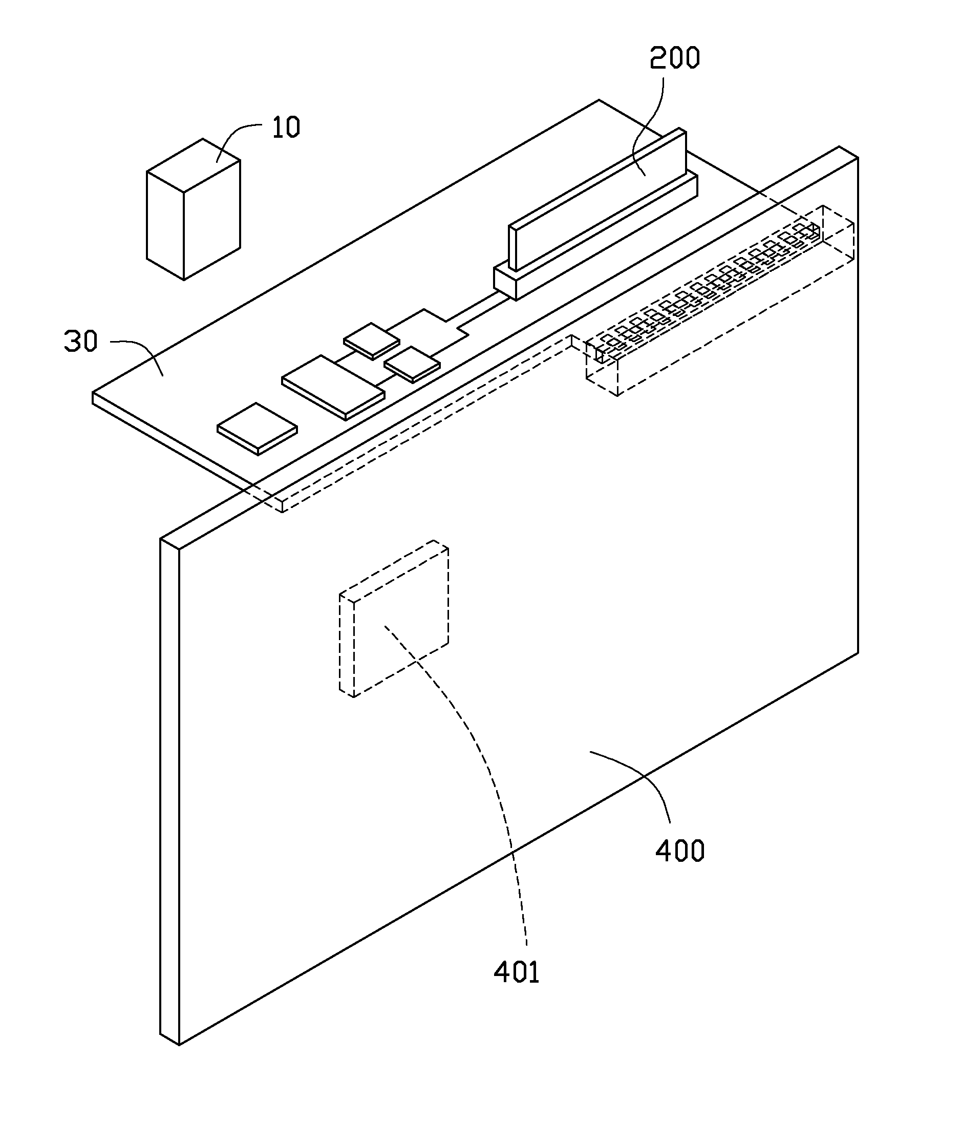
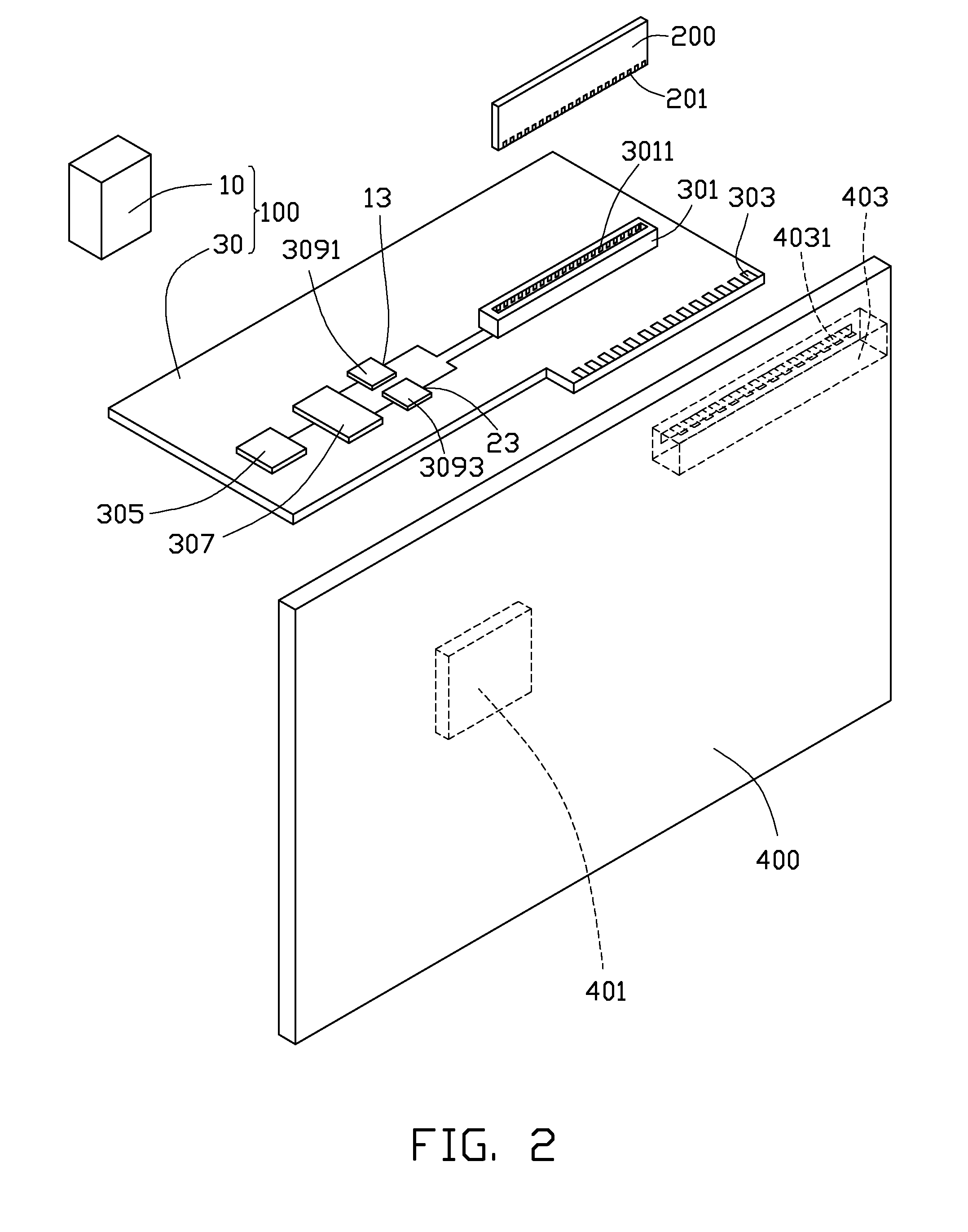
[0011]Referring to FIGS. 1, 2 and 3, a motherboard alarm system test circuit 100, in accordance with an exemplary embodiment, is shown. The motherboard alarm system test circuit 100 is configured for testing a memory alarm system 401 of a motherboard 400. The motherboard alarm system test circuit 100 includes an infrared emitter 10, and a circuit board 30, and a memory 200 having a plurality of edge connectors (first golden fingers 201).

[0012]The infrared emitter 10 is configured for emitting infrared light, and includes two control buttons (not shown). When one of the two control buttons is actuated, the infrared emitter 10 emits a first infrared light. When the other control button is actuated, the infrared emitter 10 emits a second infrared light.

[0013]The circuit board 30 includes a memory slot 301, a plurality of edge connectors (second golden fingers 303), an infrared receiver 305, a signal chip computer 307 el...


PUM


Abstract

A motherboard alarm system test circuit includes an infrared emitter, a memory, and a circuit board. The circuit board includes a memory slot, many edge connectors, an infrared receiver, a single chip computer, and a switch circuit. The memory slot includes many spaced metal sheets. One end of each metal sheet is electrically connected to one of the first golden fingers of the memory. Each edge connector is electrically connected to the other end of each metal sheet. The second golden fingers of the circuit board are electrically connected to the memory slot. The signal chip computer includes an input pin electrically connected to the infrared receiver. The switch circuit is electrically connected to the signal chip computer. The switch circuit controls an electrical connection between the plurality of metal sheets and the plurality of first golden fingers of the memory.

Description

BACKGROUND[0001]1. Technical Field[0002]The present disclosure relates to motherboard alarm systems, and particularly, to a motherboard alarm system test circuit.[0003]2. Description of Related Art[0004]In a process of testing a computer, testing a motherboard alarm system is a very important test. For example, when a fault occurs in a memory of a motherboard, a loudspeaker of the motherboard will sound an alarm, or an indicator light of the motherboard will illuminate.[0005]When the motherboard alarm system is tested, a particular connection of the memory is manually grounded via wires, to set the connection at a low level voltage. In such case, a fault will occur in the memory. If the motherboard alarm system outputs an alarm in this case, the motherboard alarm system is in a normal state. If the motherboard alarm system does not output an alarm, the motherboard alarm system is in an abnormal state, and the motherboard alarm system needs to be checked and repaired. In addition, an...

Claims


Application Information

Patent Timeline
IPC IPC(8): G01R31/00
CPCG06F11/22G06F11/2215
Inventor TU, YI-XINZHANG, GUO-FENGPENG, ZHENG-QUANZHOU, HAI-QING
Owner HONG FU JIN PRECISION IND (SHENZHEN) CO LTD
Features
  • Generate Ideas
  • Intellectual Property
  • Life Sciences
  • Materials
  • Tech Scout
  • Unparalleled Data Quality
  • Higher Quality Content
  • 60% Fewer Hallucinations
Learn More