Efficient Selective Catalyst Reduction System

a selective catalyst and gas turbine engine technology, applied in the direction of machines/engines, separation processes, mechanical equipment, etc., can solve the problems of gas turbine engine systems not being in compliance with current governmental emissions regulations, nitrogen oxide emissions may also spike during transient operation,

Inactive Publication Date: 2013-02-07
GENERAL ELECTRIC CO
View PDF6 Cites 45 Cited by
  • Summary
  • Abstract
  • Description
  • Claims
  • Application Information

AI Technical Summary

Benefits of technology

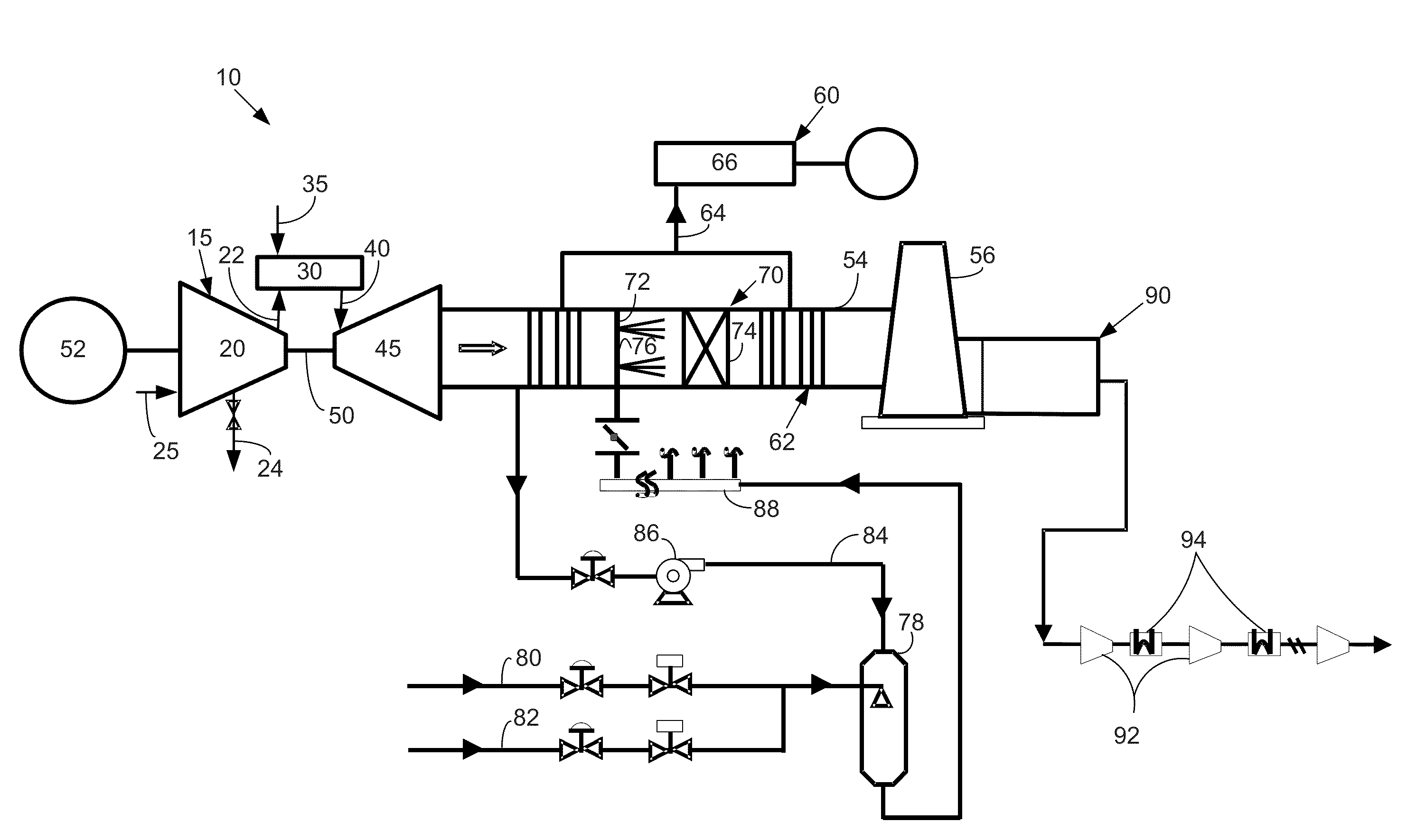
[0006]The present application and the resultant patent thus provide a gas turbine engine system. The gas turbine engine system may include a gas turbine engine producing a flow of combustion gases, an emissions reduction system in communication with the gas turbine engine, a flow of ammonia to be injected into the flow of combustion gases, and a source of compressed gas to vaporize the flow of ammonia.

Problems solved by technology

Further, nitrogen oxide emissions also may spike during transient operation conditions such as during engine startup, load swing conditions, and the like.
These nitrogen oxide output spikes may result with the gas turbine engine system being out of compliance with current governmental emissions regulations.

Method used


Image

  • Efficient Selective Catalyst Reduction System
  • Efficient Selective Catalyst Reduction System
  • Efficient Selective Catalyst Reduction System

Examples


Embodiment Construction

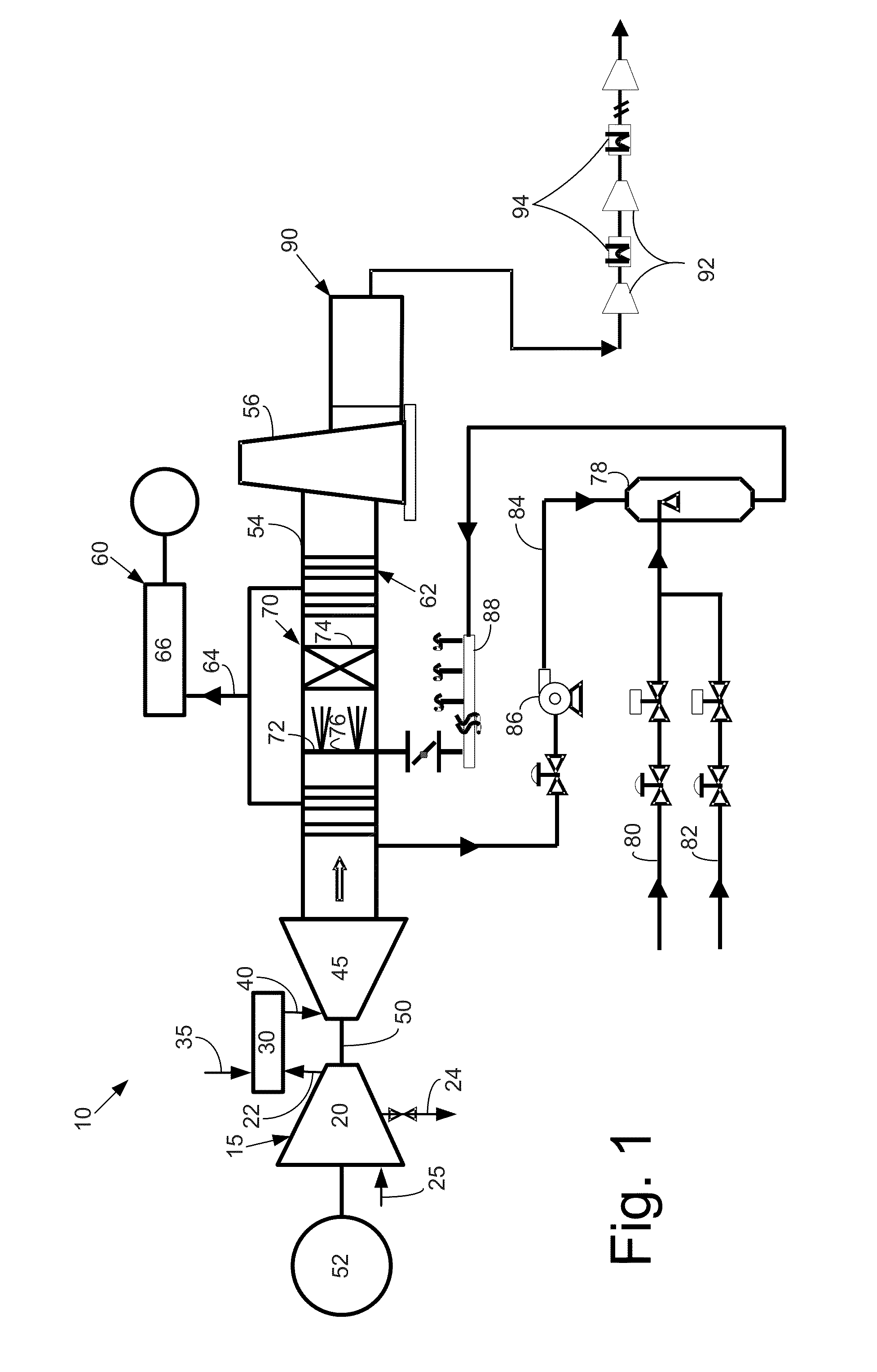
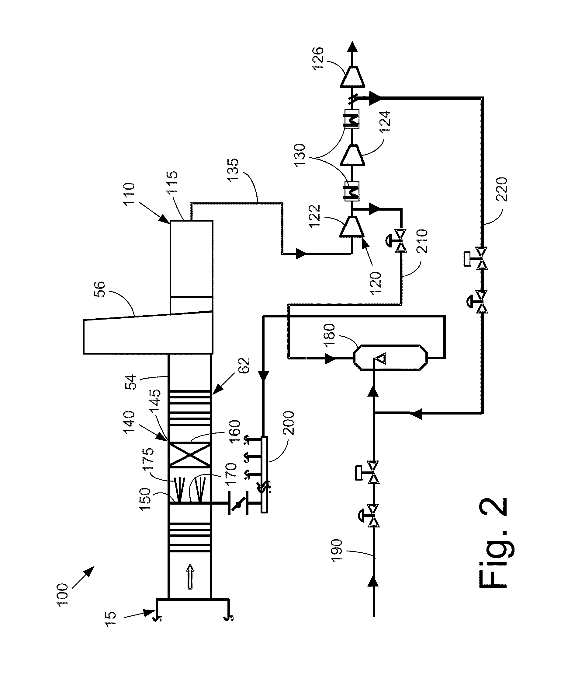
[0019]Referring now to the drawings, in which like numerals refer to like elements throughout the several views, FIG. 1 shows a schematic view of a gas turbine engine system 10 as may be used herein. The gas turbine engine system 10 may include one or more gas turbine engines 15. Each gas turbine engine 15 may include a compressor 20. The compressor 20 compresses an incoming flow of air 25. The compressor 20 delivers the compressed flow of air 25 to a combustor 30. The combustor 30 mixes the compressed flow of air 25 with a compressed flow of fuel 35 and ignites the mixture to create a flow of combustion gases 40. Although only a single combustor 30 is shown, the gas turbine engine 15 may include any number of combustors 30. The flow of combustion gases 40 is in turn delivered to a turbine 45. The flow of combustion gases 40 drives the turbine 45 so as to produce mechanical work. The mechanical work produced in the turbine 45 drives the compressor 20 via a shaft 50 and an external l...


PUM

PropertyMeasurementUnit
temperatureaaaaaaaaaa
mechanical workaaaaaaaaaa

Abstract

The present application provides a gas turbine engine system. The gas turbine engine system may include a gas turbine engine producing a flow of combustion gases, an emissions reduction system in communication with the gas turbine engine, a flow of ammonia to be injected into the flow of combustion gases, and a source of compressed gas to vaporize the flow of ammonia.

Description

TECHNICAL FIELD[0001]The present application and the resultant patent relate generally to gas turbine engine systems and more particularly relate to a gas turbine engine system having a selective catalyst reduction system driven by captured carbon dioxide or other types of gases.BACKGROUND OF THE INVENTION[0002]Generally described, carbon dioxide (“CO2”) produced in power generation facilities and the like is considered to be a greenhouse gas. As such, governmental regulations generally require the capture and sequestration of the carbon dioxide produced in the overall power generation process as opposed to venting into the atmosphere. Specifically, the carbon dioxide may be compressed and intercooled in a number of stages to reach a supercritical state. The carbon dioxide then may be liquefied and transported for end usage such as deep ocean sequestration, enhanced oil recovery, or other uses.[0003]Likewise, power generation equipment produces nitrogen oxides (NOx) and other gasses...

Claims


Application Information

Patent Timeline
Patent Type & Authority Applications(United States)
IPC IPC(8): F02C7/00
CPCB01D53/8631B01D2259/124F01N2610/02F01N2610/08F01N2610/14Y02T10/24B01D53/62B01D53/90B01D53/9431B01D2251/2062B01D2256/12B01D2256/22B01D2257/404B01D2257/504B01D2258/0283Y02C10/04F01N3/2066Y02C20/40Y02T10/12
Inventor MERCHANT, LAXMIKANTSAHA, RAJARSHIMAZUMDER, INDRAJITSARMA, VEDHANABHATLAHOSKIN, ROBERT FRANKKRAEMER, GILBERT O.
Owner GENERAL ELECTRIC CO
Why Eureka
Try Eureka