Backlight

a backlight and light technology, applied in the field of backlight, can solve the problems of cross talk and consequent image degradation, difficult to achieve high collimated output with good light extraction efficiency and uniformity, and inability to achieve collimation. , the effect of loss

Inactive Publication Date: 2013-02-07
SHARP KK
View PDF7 Cites 22 Cited by
  • Summary
  • Abstract
  • Description
  • Claims
  • Application Information

AI Technical Summary

Benefits of technology

[0017]According to another aspect, a radiant exitance at a plane immediately above the lens array varies by less than 50% over an area of the backlight.
[0018]According to yet another aspect, the light collimated by the lens array is such that more than 90% of the light power is contained within an angular cone with a half-width of 10 degrees.

Problems solved by technology

If it enters an incorrectly addressed chamber, cross talk and consequent image degradation occurs.
Lightguide-based backlights have the advantage of being thin and requiring relatively few primary light sources such as LEDs, but attaining highly collimated output with good light extraction efficiency and uniformity has proven difficult.
Any collimation is, however, necessarily lost after passing through such a diffuser.
Even without local dimming, direct view backlights can give higher efficiency than lightguide ones, since the injection of light into a lightguide and the extraction of light from a lightguide are inherently lossy processes, particularly when uniformity is demanded.
The spatial uniformity in the light field reflected from the mirror is, however, poor, as will be illustrated by an example below.
A real SRLED will not give perfectly collimated light due to the finite extent of the emitting surface, imperfections in the mirror geometry, etc.
The SRLED array gives collimated but spatially non-uniform output.
One or more diffuser sheets are used to spatially homogenise the output but the collimation is then lost.

Method used


Image

  • Backlight
  • Backlight
  • Backlight

Examples


first embodiment

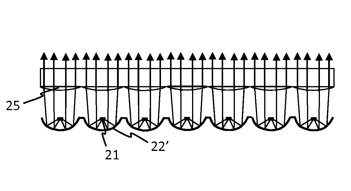
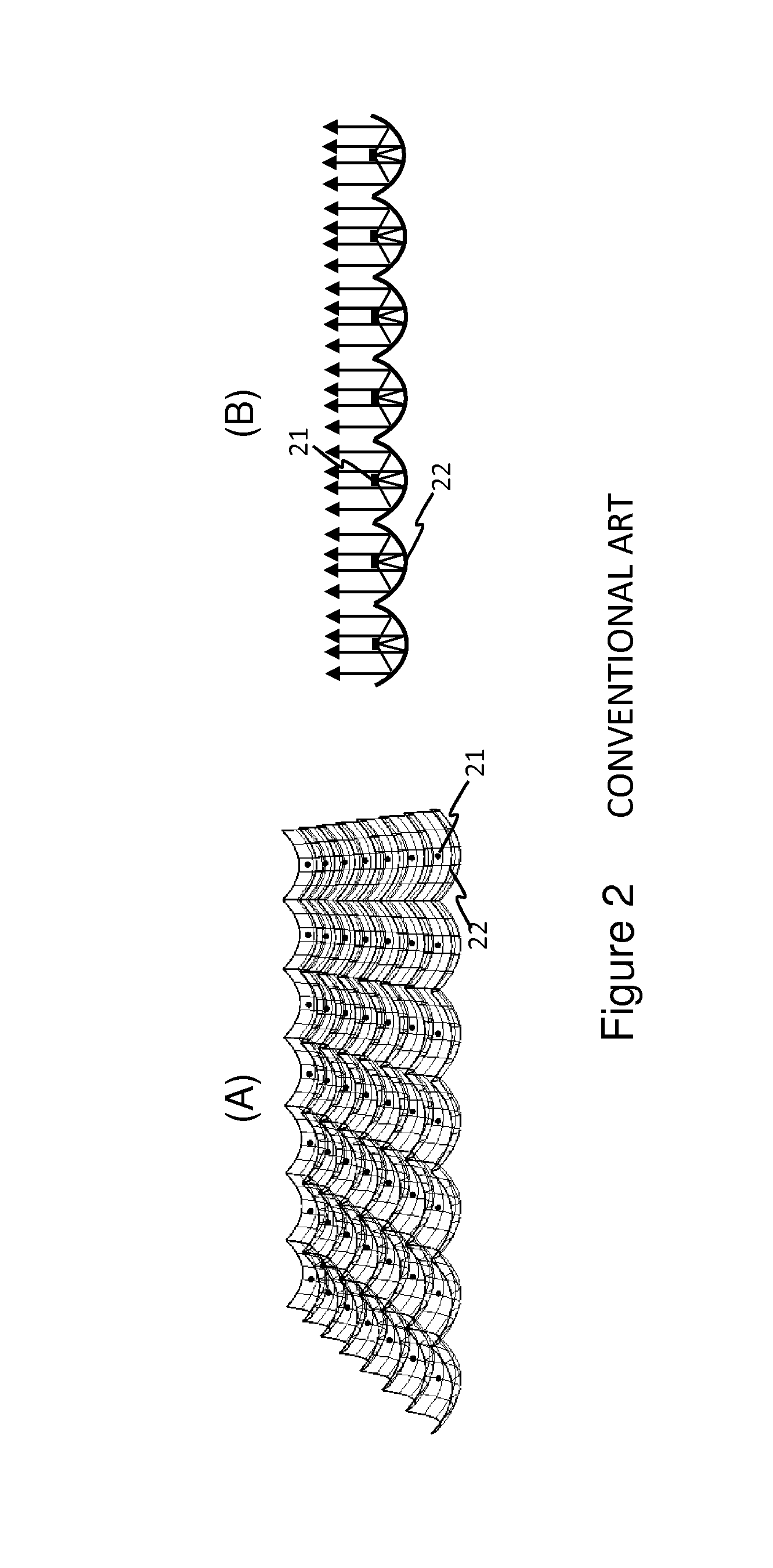
[0088]The present invention provides a means of attaining spatial uniformity with highly collimated output with a much reduced device thickness. FIG. 4 illustrates the invention. FIG. 4(A) shows a 3-dimensional rendering of the geometry and 4(B) shows a cross-section including sample ray paths. In contrast to the backlight of FIG. 2, mirrors 22′ within the mirror array are not parabolic in shape and do not give collimated output after light from primary light sources 21 is reflected in them. A collimating lens sheet 25 made up of a lens array is used to collimate the light reflected by the mirror array. Each lens in the lens array is registered with a corresponding mirror 22′ in the mirror array. The mirror shape, lens shape, light source position and the separation between the mirror and lens sheet are carefully chosen to attain spatial uniformity as well as collimation in the light leaving the lens sheet 25.

[0089]The backlight includes a tiled array of single reflection light emit...

second embodiment

[0095]FIG. 6 shows a second embodiment where a lens cap 31 is placed over the LED to change the angular properties. Two configurations are shown. In the first, shown in FIG. 6(A), the lens cap 31 is purely refractive. More light is sent to higher angles from the axial direction than from the naked emitter. Specifically, the lens cap 31 alters the emission angular profile so that more light radiance is present at higher values of θ (but within the range 0°31′ causes total internal reflection of light rays emitted close to the axial direction of the mirror and lens. This can allow more light reflected at the mirrors to be steered away from the primary light sources. Both configurations enable more light to be prevented from impinging on the LED structure after reflection in the mirror. The form shown in FIG. 6(B) is particularly suited to steering light from the LED.

third embodiment

[0096]FIG. 7 shows a third embodiment in which the top lens sheet is replaced by an array of Fresnel lenses 25′. This enables a slightly thinner backlight to be realized and reduces the backlight weight. These are important design considerations in any mass produced display system.


PUM


Abstract

A backlight is provided for an at least partially transmissive display or another lighting application. The backlight comprises an array of primary light sources that emit downwards towards an arrangement of curved mirror surfaces. The light reflected by the mirror surfaces is collimated by an arrangement of lenses. The mirror surface shape, lens shape, primary light source positions and the separation between the lens and mirror surfaces are chosen to ensure a high degree of spatial uniformity as well as collimation.

Description

TECHNICAL FIELD[0001]The present invention relates to a backlight, for example for use with an at least partially transmissive spatial light modulator. The present invention also relates to a display including such a backlight. Moreover, the present invention relates to a distributed illumination panel that may be used for general illumination.[0002]In particular, the invention relates to maintaining high spatial uniformity of a highly collimated direct view backlight with reduced thickness.BACKGROUND ART[0003]FIG. 1(A) shows a conventional liquid crystal display (LCD) configuration in which collimated white light from the backlight 1 is focused, by means of a lens array 2, through apertures 3 within a thin film transistor (TFT) layer associated with the display electronics. The focusing prevents light being lost by absorption or scatter in the TFT electronics. A diffusing layer 5 is added above a liquid crystal (LC) cell 6, polarizers 7 and 7′ and the TFT layer. The function of the...

Claims


Application Information

Patent Timeline
Patent Type & Authority Applications(United States)
IPC IPC(8): F21V13/04G09F13/04
CPCG09F13/14G02F2001/133607G02F1/133605G02F1/133607
Inventor ROBERTS, PETER JOHNMONTGOMERY, DAVID JAMES
Owner SHARP KK
Why Eureka
Try Eureka