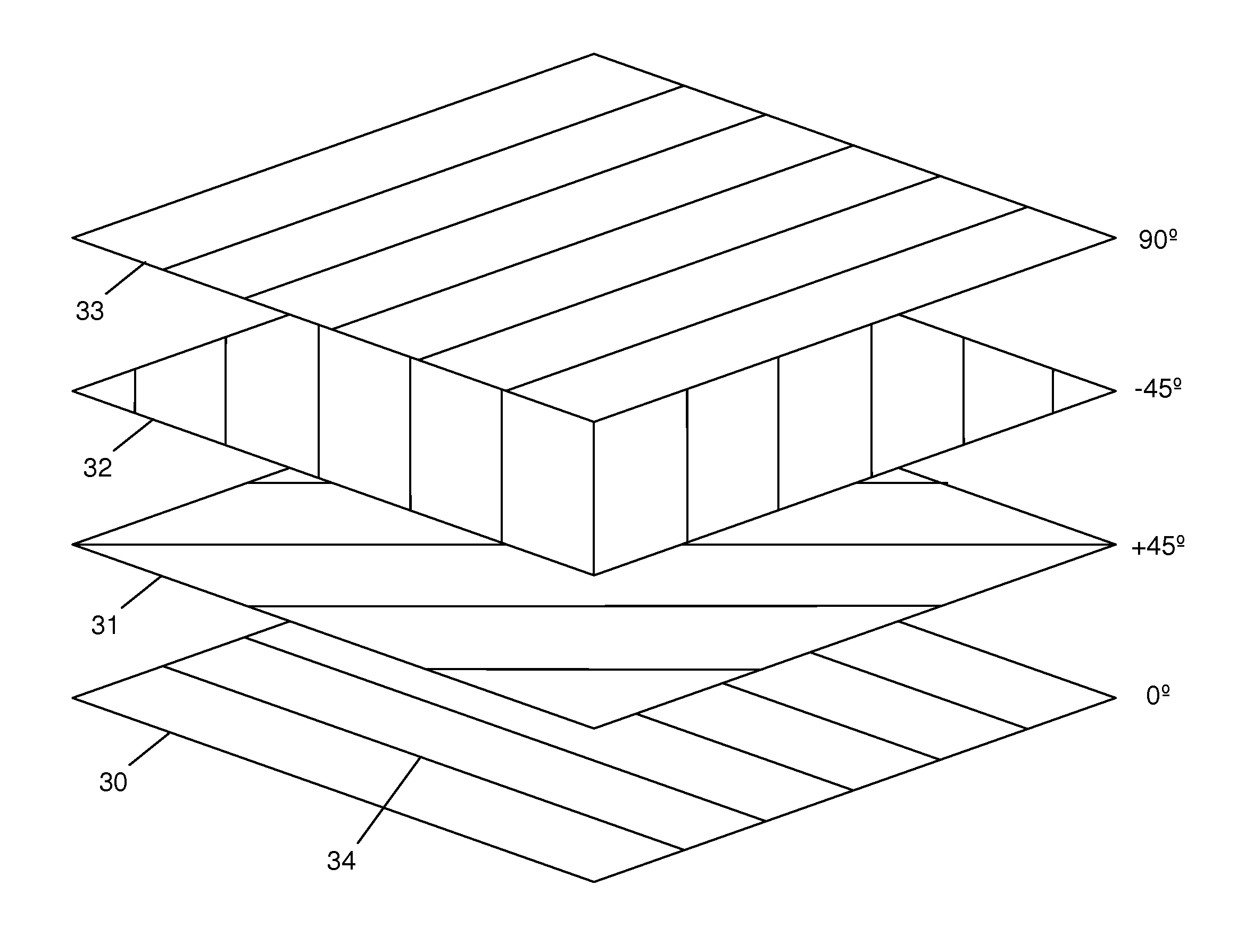
Composite structure

a composite structure and composite material technology, applied in the field of composite materials, can solve the problems of thermally induced distortion of manufacturing, unbalanced ply sets, etc., and achieve the effect of simplifying the design

Active Publication Date: 2013-02-07
AIRBUS OPERATIONS LTD
View PDF4 Cites 21 Cited by
  • Summary
  • Abstract
  • Description
  • Claims
  • Application Information

AI Technical Summary

Benefits of technology

[0011]As well as having + / −45° plies the structure may have additional bias plies at other angles. However, preferably the structure has only four ply orientations, at least in the first and second regions, in order to simplify the design.

Problems solved by technology

This provides a compromise between the advantages of using un-balanced ply sets (for instance to provide bending torsion coupling or greater stiffness in one bending direction) and the disadvantage that un-balanced ply sets can introduce thermally induced distortion during manufacture.

Method used


Image

  • Composite structure
  • Composite structure
  • Composite structure

Examples


Embodiment Construction

)

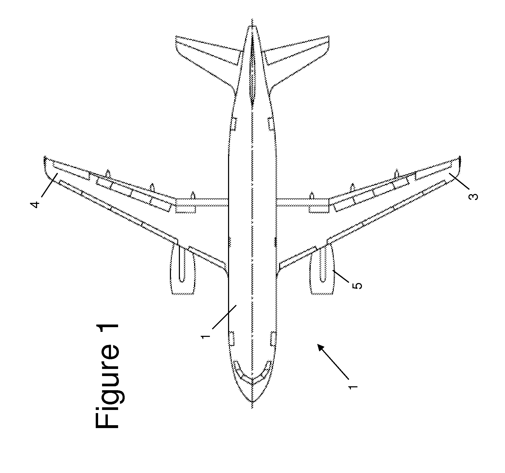
[0026]FIG. 1 is a plan view of an aircraft 1 with a fuselage 2, and port and starboard wings 3, 4. The wings 3, 4 are cantilevered structures each with a root mounted to the fuselage 2 and a principal bending axis extending outboard from the root to a free wing tip.

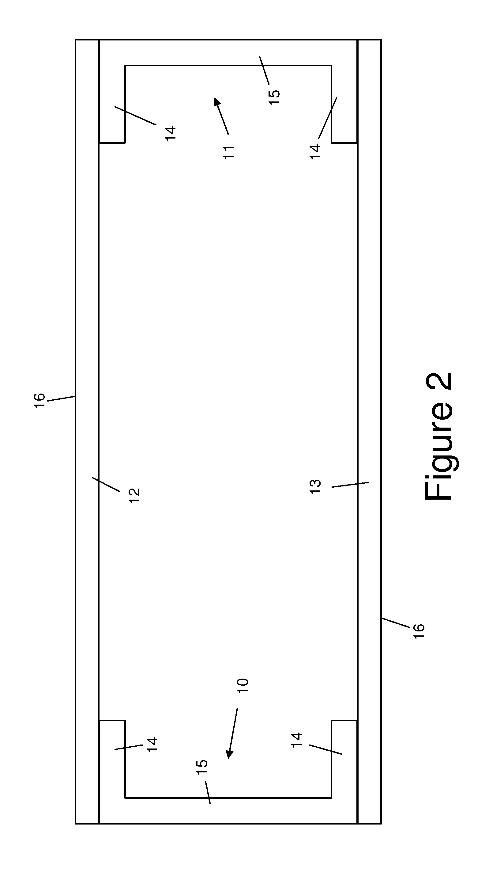
[0027]The principal structural element of each wing is a wing box shown in FIG. 2. Note that the wing box is shown schematically in FIG. 2 which omits various control surfaces (flaps, slats etc) and other details shown in FIG. 1. The wing box comprises a pair of spars 10,11 and a pair of skins 12,13 which each run along the full length of the wing box (perpendicular to the sectional view of FIG. 2). Each skin 12,13 has an outer surface 16 which forms an aerodynamic outer surface of the wing. Each spar has a pair of flanges 14 which are bolted to the skins 12,13, and a shear web 15 extending between the skins. The skins may also have attached stiffeners or stringers, which may be straight or curved in order to match the p...


PUM

PropertyMeasurementUnit
angleaaaaaaaaaa
angleaaaaaaaaaa
angleaaaaaaaaaa

Abstract

A structure comprising a plurality of plies of fibre-reinforced composite material, each ply having a ply orientation defined by a principal stiffness direction of the ply. The structure has a first region and a second region, each region comprising N1 primary plies, N4 cross plies with a ply orientation substantially perpendicular to the primary plies, N2 positive-angled bias plies with a ply orientation at a positive acute angle to the primary plies, and N3 negative-angled bias plies with a ply orientation substantially perpendicular to the positive-angled bias plies. The ply orientation of the primary plies in each region is more closely aligned with a primary axis of the structure than the cross plies or the bias plies. N1=N4 in the first region but not in the second N region, and N2=N3 in the second region but not in the first region. In each of the two regions, one ply set is balanced and the other ply set is un-balanced. This provides a compromise between the advantages of using un-balanced ply sets, for instance to provide bending torsion coupling, and the disadvantage that un-balanced ply sets can introduce thermally induced distortion during manufacture.

Description

FIELD OF THE INVENTION[0001]The present invention relates to a structure comprising a plurality of plies of fibre-reinforced composite material.BACKGROUND OF THE INVENTION[0002]In composite structures of this type, each ply has a ply orientation defined by principal stiffness direction of the ply. For example the structure may have a lay-up with primary plies, cross plies with a ply orientation substantially perpendicular to the primary plies, positive-angled bias plies with a ply orientation at a positive acute angle to the primary plies, and negative-angled bias plies with a ply orientation substantially perpendicular to the positive-angled bias plies. Typically the ply orientation of the primary plies is more closely aligned with a principal bending axis of the structure than the cross plies or the bias plies. It is known to vary the lay-up in order to achieve desired physical characteristics. For instance the proportion of primary plies may be increased in order to increase the ...

Claims


Application Information

Patent Timeline
Patent Type & Authority Applications(United States)
IPC IPC(8): B32B5/12
CPCB29C70/202B29L2031/085B29L2031/3085B64C3/26Y10T428/24124Y10T428/24058Y10T428/24Y10T428/24174Y02T50/433Y02T50/40Y02P70/50
Inventor MEYER, JONATHANMATTHEWS, MICHAEL
Owner AIRBUS OPERATIONS LTD
Why Eureka
Try Eureka