

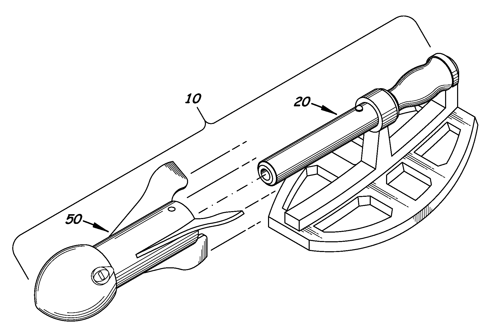
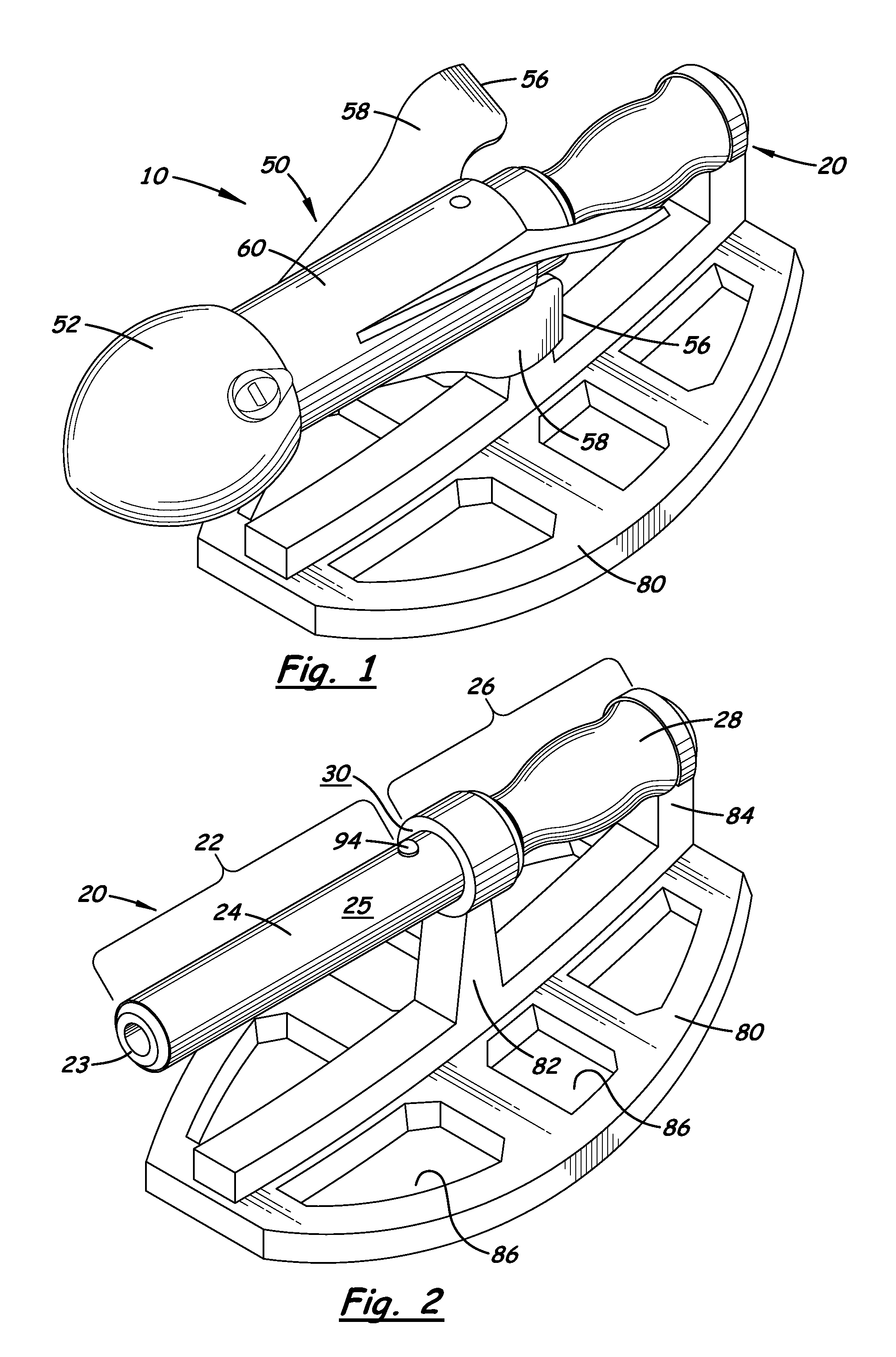
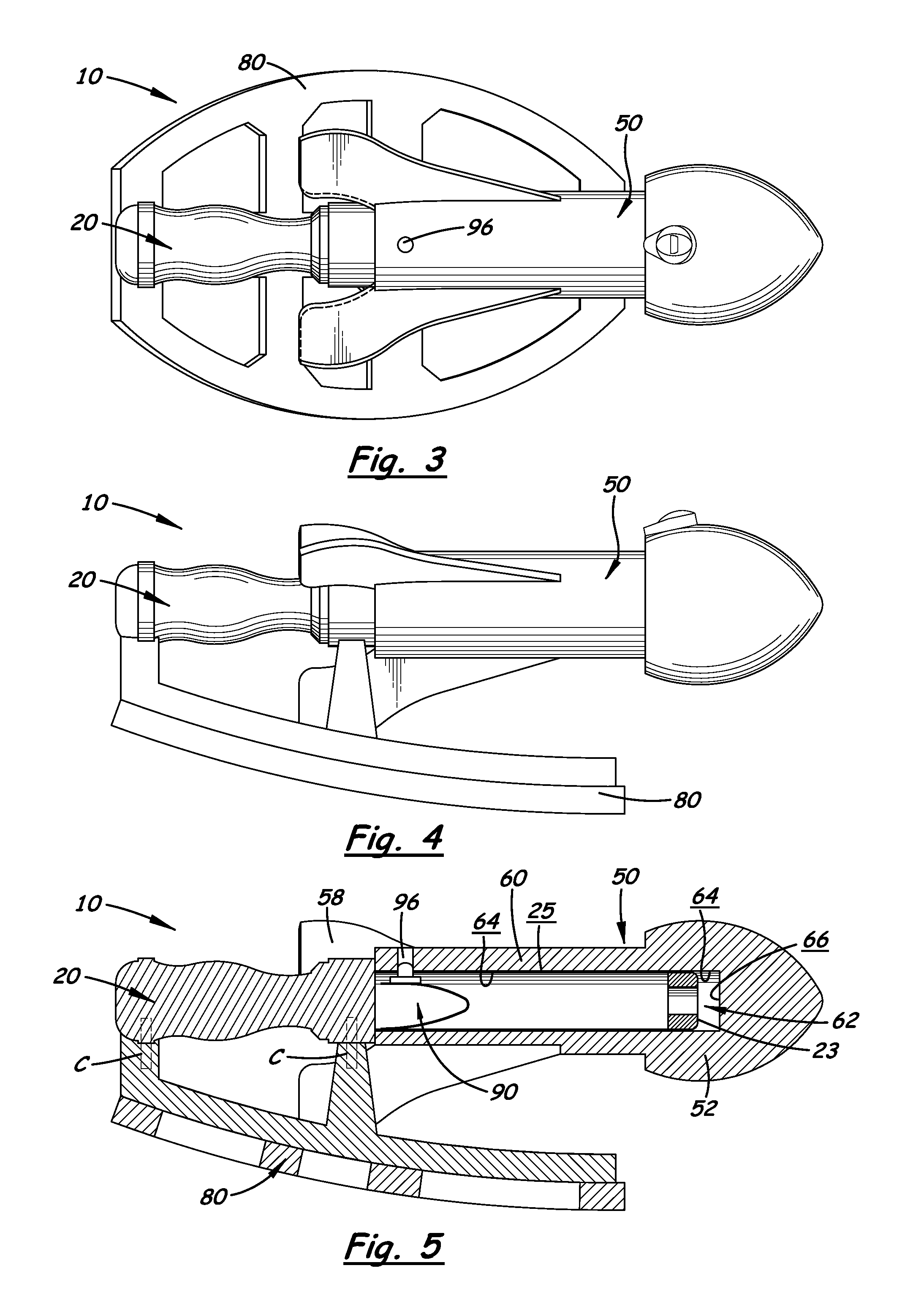
Toy for flinging missile or other projectile
a projectile and toy technology, applied in toys, mechanical vibration separation, white arms/cold weapons, etc., can solve the problems of limited friction/interference of the engagement system, and achieve the effect of improving the control of the launcher
- Summary
- Abstract
- Description
- Claims
- Application Information
AI Technical Summary
Benefits of technology
Problems solved by technology
Method used
Image

Examples
Embodiment Construction
Objects of Certain Embodiments of the Invention
[0043]Objects of the invented toy device for flinging missile or other projectile may include one or more objects from the following paragraphs.
[0044]The device may be a safe, multi-use toy (for launching, throwing, catching, target use, and combat play) that effectively and efficiently launches larger and heavier foam type missiles with great performance, in terms of both accuracy and distance. The device may easily and effectively launch a multitude of generally-missile-shaped aerodynamic toys, including, but not limited to, missiles, darts, arrows, and bullets. Other ballistic shapes, such as footballs, baseballs, basketballs and the like, may be used partially or fully for the missile head and are combined with a body having preferably three or more tail fins near the body end.
[0045]The device uses centrifugal force in the form of a flinging / slinging arm motion by the user that does not require the user to press or release a button ...
PUM
 Abstract
Description
Claims
Application Information