Installation structure for charging equipment in rear vehicle body

a technology for installing structures and charging equipment, which is applied in the direction of charging stations, vehicle sub-unit features, transportation and packaging, etc. it can solve the problem of developing a new special vehicle body, and achieve the effect of reducing the waving of the outlet cable, preventing great load, and convenient installation of charging equipmen

Active Publication Date: 2013-02-14
SUZUKI MOTOR CORP
View PDF3 Cites 6 Cited by
  • Summary
  • Abstract
  • Description
  • Claims
  • Application Information

AI Technical Summary

Benefits of technology

[0012]The present invention attains the following advantageous effects. The installation structure for charging equipment in a rear vehicle body of the present invention includes a rear floor panel disposed in the horizontal direction in the rear vehicle body; a spare tire housing disposed at a position with a distance in a longitudinal direction of the vehicle from a rear edge of a rear floor panel, the spare tire housing having a recessed shape projecting downward of the vehicle; a charger for charging a battery mounted on the vehicle, which is disposed in the spare tire housing; a charging connector connected to the charger through an outlet cable, and the charging connector is configured to be capable of supplying power to the charger; in the installation structure for charging equipment in a rear vehicle body, the charging connector is disposed rearward of the vehicle in the spare tire housing, an insertion hole is formed in a peripheral wall of the spare tire housing, a cover member is joined to the rear floor panel so as to form a closed cross section, the cover member is disposed to extend from the peripheral wall of the spare tire housing toward the charging connector so as to communicate space defined by the closed cross section with the insertion hole, and the outlet cable is disposed so as to be inserted through the insertion hole and the space defined by the closed cross section. Hereby, it is possible to install the outlet cable for connecting the charger and the charging connector all the way around in a short route passing through the insertion hole with less waving of the cable in the vertical and lateral directions. Specifically, it is unnecessary to install the outlet cable along the bottom of the spare tire housing in the horizontal direction, along the peripheral wall of the spare tire housing in the vertical direction, and then along the upper face of the rear floor panel in the horizontal direction, and also to install the outlet cable all the way around to avoid the structures on the upper face of the rear floor panel, as the prior art does. Accordingly, it is possible to readily install the charging equipment such as the charger, the charging connector, and the outlet cable. Reduction of waving of the outlet cable in the vertical and lateral directions prevents great load from being applied to the outlet cable. Since the outlet cable is surrounded by the cover member and the insertion holes provided in the spare tire housing so as to insert the outlet cable is also surrounded by the cover member, it is possible to prevent deterioration of the charging equipment due to external factors such as muddy water and stones. Since the insertion hole of the spare tire housing is reinforced by the cover member, enhancement can be attained in rigidity of the rear vehicle body, particularly rigidity of the rear vehicle body against load applied from the rear of the vehicle body.
[0013]In the installation structure for charging equipment in a rear vehicle body of the present invention, the insertion hole is disposed in the peripheral wall rearward of the vehicle in the spare tire housing; thus load applied from the rear of the vehicle body can be easily transferred to the peripheral wall rearward of the vehicle in the spare tire housing through the cover member. Accordingly, enhancement can be attained in rigidity of the rear vehicle body and the charging equipment can be readily installed.
[0014]In the installation structure for charging equipment in a rear vehicle body of the present invention, the cover member extends from the peripheral wall of the spare tire housing to a rear edge of the rear floor panel; thus it is possible to securely prevent deterioration due to external factors such as muddy water and stones, as well as to readily install the charging equipment.

Problems solved by technology

Unfortunately, it is costly to develop a new special vehicle body, and thus it has been desired to develop an environmentally friendly vehicle at low cost.

Method used


Image

  • Installation structure for charging equipment in rear vehicle body
  • Installation structure for charging equipment in rear vehicle body
  • Installation structure for charging equipment in rear vehicle body

Examples


Embodiment Construction

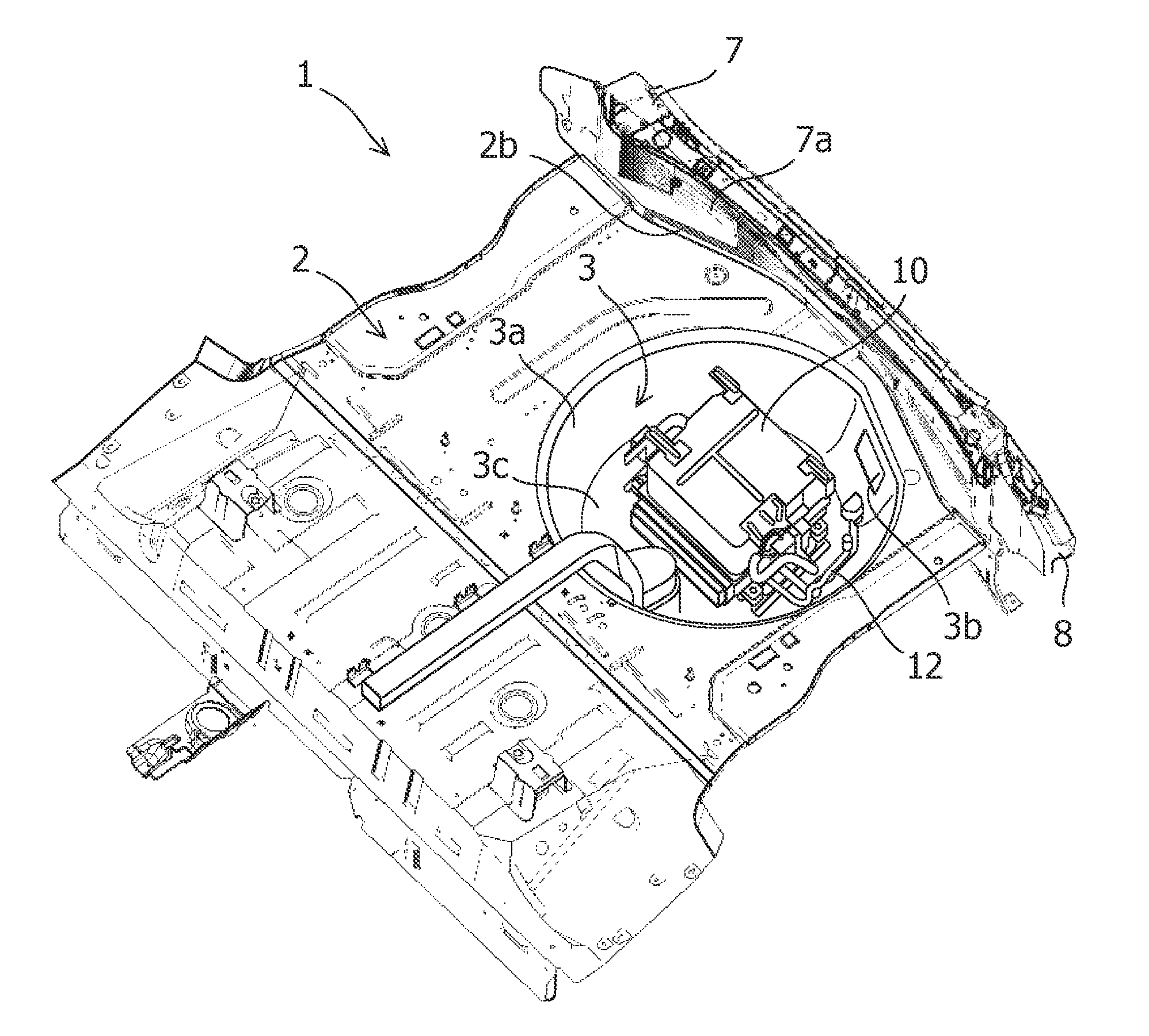
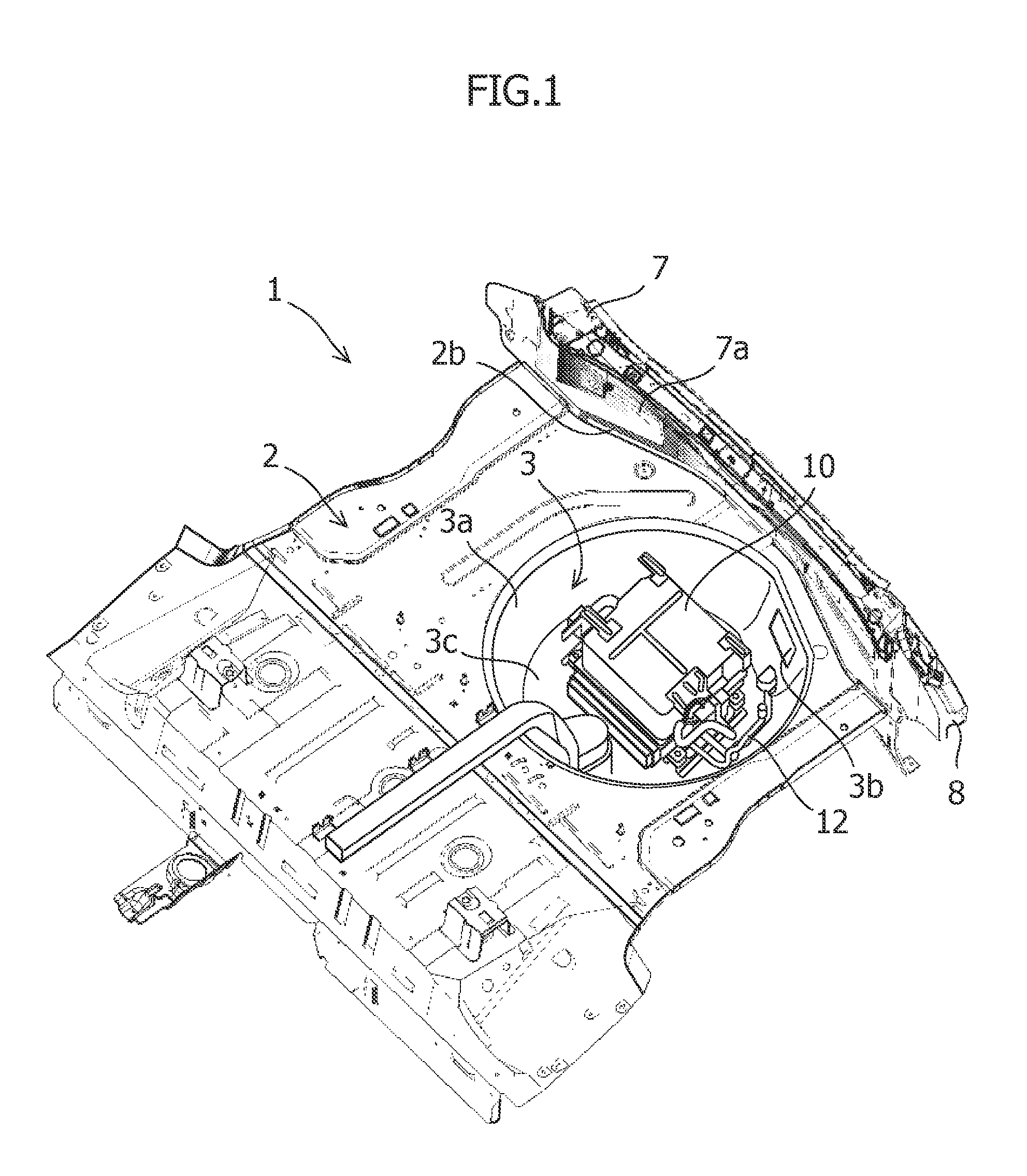
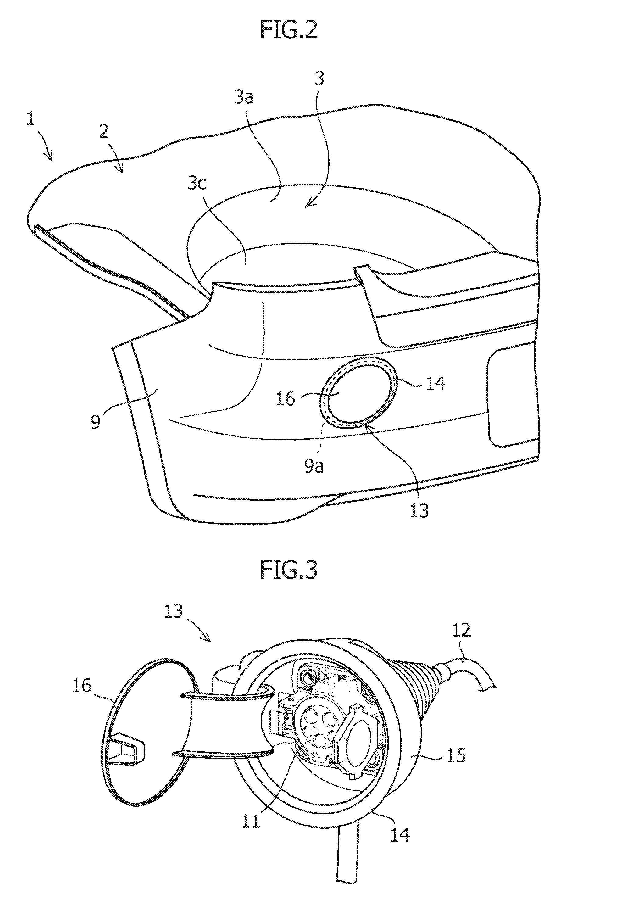
[0020]Hereinafter, with reference to FIG. 1 to FIG. 5, description will be provided on the installation structure for charging equipment in a rear vehicle body (referred to as the “installation structure”, hereinafter) 1 according to the embodiment of the present invention. The rear floor panel 2 is provided in the rear vehicle body. The spare tire housing 3 in a recessed shape projecting downward of the vehicle body is formed in the rear floor panel 2. The cover member 4 is attached onto the lower face 2a of the rear floor panel 2. The hook reinforcement member 6 for attaching the tow hook 5 is disposed onto the lower face 2a of the rear floor panel 2 in the spare tire housing 3. The back panel 7 extending in the vehicle width direction is disposed at the rear edge of the rear floor panel 2. The bumper member 8 is disposed onto the rear face 7a of the back panel 7. The outer panel 9 is disposed in the back of the back panel 7 and the bumper member 8. In the rear vehicle body, there...


PUM


Abstract

There is provided the installation structure for charging equipment in a rear vehicle body capable of enhancing rigidity of the rear vehicle body, performing roundabout installation of the outlet cable without applying large load to the cable, preventing deterioration of the charging equipment due to external factors, and readily installing the charging equipment. In the installation structure for charging equipment in a rear vehicle body, the charger 10 for charging a battery is disposed in the spare tire housing 3, the charging connector 11 connected to the charger 10 through the outlet cable 12 is disposed rearward of the vehicle in the spare tire housing 3 so as to supply power to the charger 10, the insertion hole 3b is formed in the peripheral wall 3a of the spare tire housing 3, the cover member 4 is joined to the rear floor panel 2 so as to form a closed cross section, the cover member 4 is disposed to extend from the peripheral wall 3a of the spare tire housing 3 toward the charging connector 11 so as to communicate the space defined by the closed cross section with the insertion hole 3b, and the outlet cable 12 is disposed so as to be inserted through the insertion hole 3b and the space defined by the closed cross section.

Description

TECHNICAL FIELD[0001]The present invention relates to a structure for installing charging equipment such as a charger, a charging connector, and an outlet cable for connecting the charger and the charging connector in a rear vehicle body.BACKGROUND ART[0002]Recently, an increasing number of hybrid vehicles have been widely used as environmentally friendly vehicles in consideration of the environment. Such an environmentally friendly vehicle is capable of charging a battery through an external plug such as a domestic power supply, and more plug-in hybrid vehicles and electric vehicles have begun to be used, which are driven by using power from a battery charged in such a manner.[0003]Such an environmentally friendly vehicle is equipped with a battery of a relatively large size. Not only a battery, but also charging equipment, such as a charger for charging the battery, a charging connector, and an outlet cable for connecting the charger to the charging connector, is installed in a pl...

Claims


Application Information

Patent Timeline
Patent Type & Authority Applications(United States)
IPC IPC(8): H02J7/00
CPCB62D25/087B60K2015/053B60Y2400/61B62D43/10B60L53/16Y02T10/70Y02T10/7072Y02T90/14Y02T90/16
Inventor HARA, NOBUHIKOASOU, MASAHIRO
Owner SUZUKI MOTOR CORP
Why Eureka
Try Eureka