
Magneto-impedance element and magneto-impedance senor including detection coil.

a magneto-impedance element and detection coil technology, applied in the direction of magnetic measurement, magnetic restrictions, instruments, etc., can solve the problems of linearity and sensitivity degradation, and achieve the effects of improving linearity, reducing power consumption, and improving linearity

Active Publication Date: 2013-02-14
AICHI STEEL
View PDF2 Cites 17 Cited by
  • Summary
  • Abstract
  • Description
  • Claims
  • Application Information

AI Technical Summary

Benefits of technology

The present invention relates to a magneto-impedance element that reduces dH / dt, which is caused by the pulse current and can weaken the linearity of the induced voltage output, and improves the linearity between the external magnetic field and the induced voltage. The element achieves this by forming a conductive layer around the magnetic sensitive member and connecting them with opposite directions of pulse current flow. This results in a cancelled-out magnetic field outside the magnetic sensitive member and the conductive layer and only the dMθ / dt component varying depending on the external magnetic field can be detected. The element does not require a feedback circuit, reducing power consumption. Overall, the invention provides a magneto-impedance element with improved linearity without using a feedback circuit.

Problems solved by technology

For this reason, when time at which an output voltage of the detection coil reaches a peak is varied by an external magnetic field as shown in FIG. 12, if the external magnetic field is applied, voltages are sampled at a timing deviated from time at which the output voltage reaches a peak value, so that sensitivity and linearity are deteriorated because the output voltage drops.

Method used


Image

  • Magneto-impedance element and magneto-impedance senor including detection coil.
  • Magneto-impedance element and magneto-impedance senor including detection coil.
  • Magneto-impedance element and magneto-impedance senor including detection coil.

Examples


embodiments

Embodiment 1

[0062]A magneto-impedance element and a magneto-impedance sensor according to an embodiment of the present invention will be described below with reference to FIGS. 1 to 9.

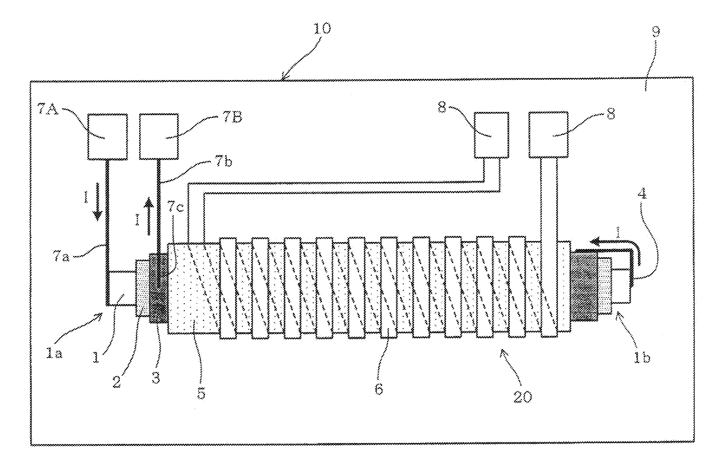
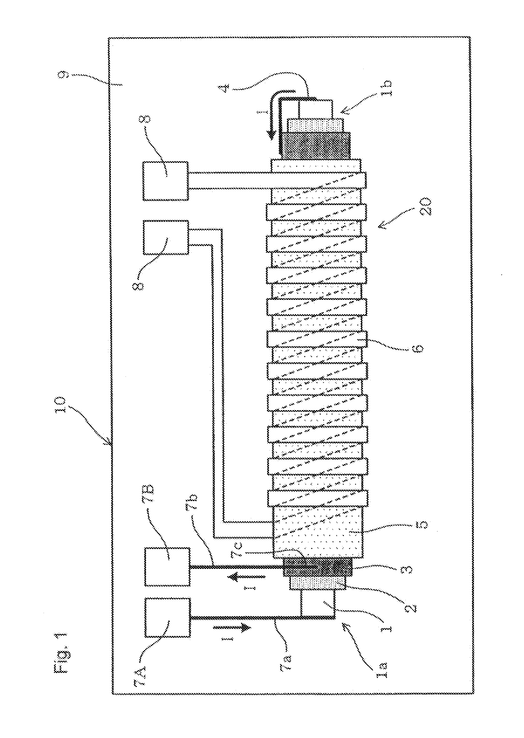
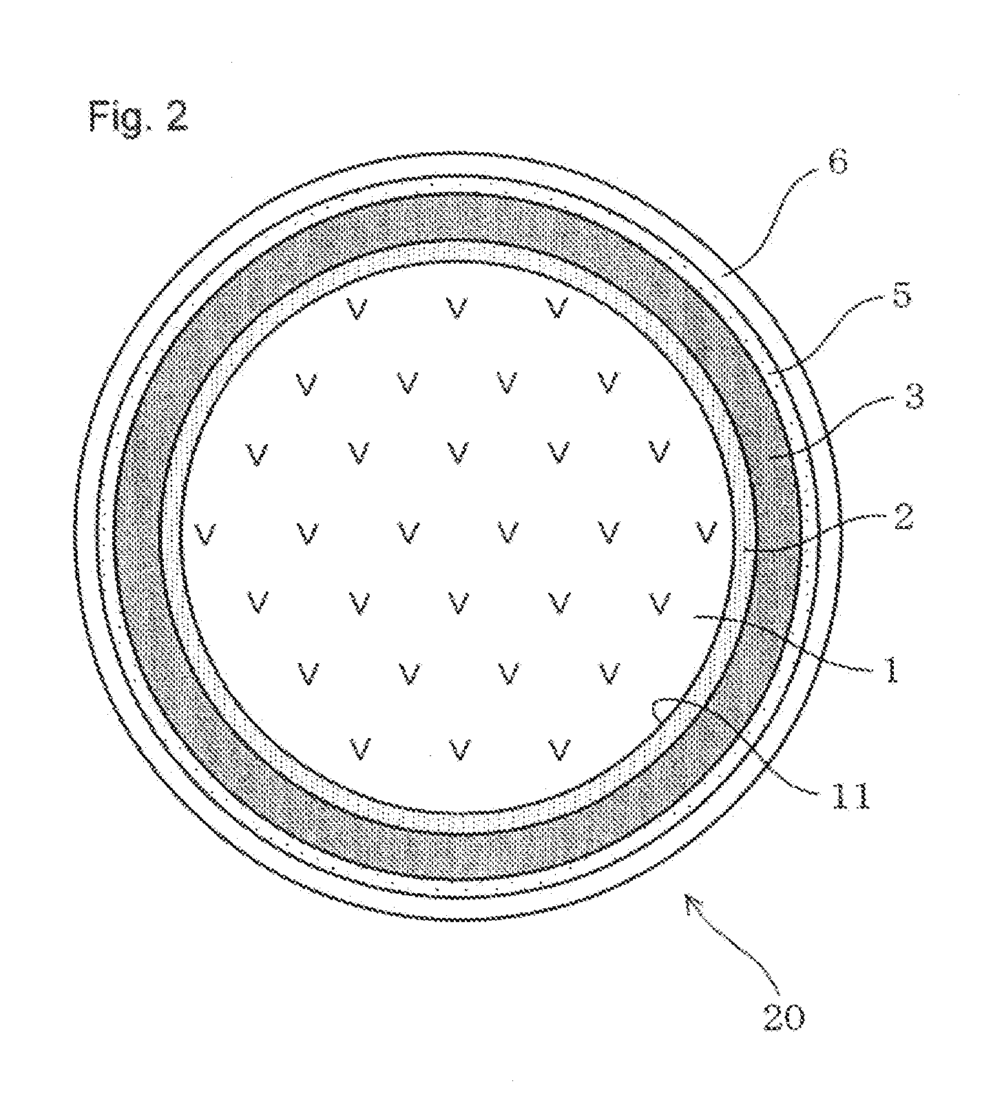
[0063]FIG. 1 is a schematic view of a magneto-impedance element 10, and FIG. 2 is a sectional view of the magneto-impedance element 10. FIG. 3 is a schematic diagram showing a flowing direction of a pulse current I.

[0064]As shown in FIG. 1, the magneto-impedance element 10 includes a magnetic sensitive member 1 having the form of a line and electromagnetic characteristics variable under the influence of a magnetic field acting from the outside, in which a pulse current I flows from one end portion 1a to the other end portion 1b in an axial direction.

[0065]A conductive layer 3 is arranged on an insulating layer 2 provided on an outer surface of the magnetic sensitive member 1.

[0066]A connection portion 4 which electrically connects the magnetic sensitive member 1 and the conductive layer 3 to each other...


PUM


Abstract

A magneto-impedance element includes a magnetic sensitive member having a form of a line, whose electromagnetic characteristics vary depending on an external magnetic field, a pulse current flowing from one to another end portion thereof in an axial direction. A conductive layer is arranged on an insulating layer provided on an outer surface of the magnetic sensitive member. A connection portion, electrically connecting the magnetic sensitive member and the conductive layer, is arranged on the other end portion in the axial direction of the magnetic sensitive member. A detection coil, outputting an induced voltage corresponding to an intensity of an external magnetic field acting on the magnetic sensitive member when the pulse current flows in the magnetic sensitive member, is wounded around the conductive layer. A direction of the pulse currents flowing in the magnetic sensitive member and in the conductive layer are opposite each other.

Description

TECHNICAL FIELD[0001]The present invention relates to a magneto-impedance element and a magneto impedance sensor having good linearity.BACKGROUND ART[0002]As a conventional magnetic sensor (hereinafter referred to as an MI sensor) using a magneto-impedance element (hereinafter referred to as an MI element), for example, a magnetic sensor having a detection coil wound around an amorphous wire is known. Patent Document 1 discloses a MI sensor which causes a pulse current to pass through an amorphous wire and measures a first pulse of an induced voltage output from a detection coil to make it possible to sensitively detect an external magnetic field Hex. The MI element is also called a giant magneto-impedance element or a GMI element. The MI sensor is also called a giant magneto-impedance sensor or a GMI sensor.[0003]Patent Document 1: Japanese Unexamined Patent Application Publication No. 2000-258517[0004]As will be described below, a principle of magnetic field detection by the MI el...

Claims


Application Information

Patent Timeline
IPC IPC(8): G01R33/02
CPCG01R33/18G01R33/063
Inventor HONKURA, YOSHINOBUYAMAMOTO, MICHIHARU
Owner AICHI STEEL
Learn More