Stationary gear unit

a technology of gear unit and gear box, which is applied in the direction of gearbox, toothed gearing, engine fuction, etc., can solve the problems of time-consuming and difficult access to wind turbines by service personnel

Active Publication Date: 2016-12-06
AUTOINVENT TRANSIP
View PDF30 Cites 0 Cited by
  • Summary
  • Abstract
  • Description
  • Claims
  • Application Information

AI Technical Summary

Benefits of technology

[0011]The difference in helix angles will operate so as to make the magnitudes of said thrusts more equal, so as to increase the extent to which said axial thrusts at least partly cancel each other out. The resultant force on the axially rigid support structure will thereby be limited. And by applying said axial thrusts to the same location of said support structure, axial movement of the input and output shafts due to varying load conditions can be minimized. As a comparison, in step-up methods of prior art, input and output shafts generally apply their respective dynamic axial thrusts onto opposite end walls of a gear unit housing, such that the gear unit housing flexes or yields somewhat under the axial load, and the input and output shafts are thereby somewhat pushed apart. Such movement may lead to premature failure of bearings, particularly under varying load conditions. Axial movement also requires a somewhat forgiving gear unit design, where substantive tooth clearance or backlash allows some freedom of movement. By instead applying the oppositely directed axial thrusts to the same location of a support structure, it is possible to obtain an axially rigid relation between the input and output shafts, such that the input and output shafts will not move significantly in the axial direction relative to each other. Hence, a gear unit with tighter backlash, and thereby increased lifetime, may be designed for such a step-up method. Throughout this disclosure, “substantially opposite directions” is to be construed as said directions forming an angle of more than 165°.
[0020]directing the drive gear axial thrust in said first direction, such that the axial thrust of the respective driven and drive gears of each layshaft at least partly cancel out within said layshaft. By canceling also at least a portion of the axial thrusts acting on each layshaft, the total resultant axial loads on a gear unit will be reduced.
[0023]In such a gear unit, when torque is supplied to the input shaft in a drive direction, axial thrust generated by the drive gear of the input shaft will be directed in said first axial direction, against said input shaft main thrust bearing arrangement. Axial thrust generated by the driven gear of the output shaft will be directed in a second axial direction, which is substantially opposite to said first axial direction. Hence, input and output shaft axial thrusts will be of opposite directions and applied to the same location, i.e. where the input and output shaft main thrust bearing arrangements are joined by the main thrust bearing support. Hence, such a gear unit may be used for carrying out the method described hereinbefore, and thereby relates to the same inventive concept. The difference in helix angles will operate so as to make the magnitudes of said thrusts more equal, so as to increase the extent to which said axial thrusts at least partly cancel each other out in the main thrust bearing support. The resultant force on the bearing support will thereby be limited. Thanks to the input and output shafts being arranged for applying their respective axial thrusts to the same, axially rigid location, axial movement of the shafts is reduced. This allows for tighter gearing backlash, which prolongs service life of the gear unit. Furthermore, reduced axial movement reduces so-called skidding, a phenomenon that will be described in more detail below. Similar to “substantially opposite directions”, the term “substantially parallel” is to be construed as forming an angle of less than 15°.
[0029]According to an embodiment of any of the gear units described hereinbefore, said input shaft is connected to a rotary power source for driving the input shaft in said driving direction of rotation, and the hand of said drive gear of said input shaft is oriented for applying input shaft axial thrust in said first axial direction when the rotary power source transmits torque to the input shaft in said driving direction. Implicitly, the axial thrust of the output shaft will thereby be applied in said second axial direction substantially opposite to said first axial direction. By having the gear unit connected to a rotary power source, for receiving rotary power primarily in said drive direction therefrom, it is possible to design the gear unit so as to withstand a larger torque in the predetermined driving direction than in a direction of rotation opposite to said driving direction. Thereby, weight may be saved and the construction may be simpler, since thrust bearing(s) may be unidirectional, and / or housing walls may be made thinner.
[0030]According to an embodiment of any of the gear units described hereinbefore, each of said input and output shafts is axially preloaded in a preloading arrangement. Each of said input and output shafts may be preloaded in a preload arrangement either between a pair of auxiliary preload bearings, or between a main thrust bearing arrangement and an auxiliary preload bearing. In the latter case, the main thrust bearing arrangement will have the double function of cancelling out dynamic axial loads, and acting as one of the preload bearings of a preloading arrangement. The auxiliary preload bearings may be located e.g. at the respective end walls of a gear unit housing. By directing the dynamic axial thrust to a single, axially rigid location, where the thrusts at least partly cancel out when the gear unit is driven in a forward, high-load drive direction, the magnitude of the preload force can be selected more freely and with a higher accuracy. In the case of tapered roller bearings, an accurate axial preloading reduces skidding and brings a greater portion of a bearing's rolling elements in contact with bearing inner and outer races during a greater portion of each turn of the respective shaft, thereby sharing the axial load more accurately between the rolling elements. For this reason, a correctly preloaded thrust bearing generally has a longer life expectancy than a non-preloaded thrust bearing. However, a too highly preloaded thrust bearing generally has a shorter life expectancy than a non-preloaded bearing. By cancelling out a significant portion of the dynamic axial forces, the preload of the shafts can be kept on a lower, more constant, and more accurately selectable level. Furthermore, any housing or support structure carrying the preload thrust bearings may be dimensioned rigid enough for the static preload, without becoming excessively heavy as it would have been if required to take up heavy dynamic axial thrusts originating from operation of helical gears as well. It also becomes possible to arrange the preload thrust bearings in a flexible support so as to provide a selected, constant axial preloading force. Still further, axial preloading also to some extent reduces the axial and radial movement of the respective shafts, thereby prolonging service life expectancy.

Problems solved by technology

At the same time, the construction needs to be robust and tolerant to weather and load, since a remote wind turbine location may make the wind turbine difficult and time consuming for service personnel to access.

Method used


Image

  • Stationary gear unit
  • Stationary gear unit
  • Stationary gear unit

Examples


Embodiment Construction

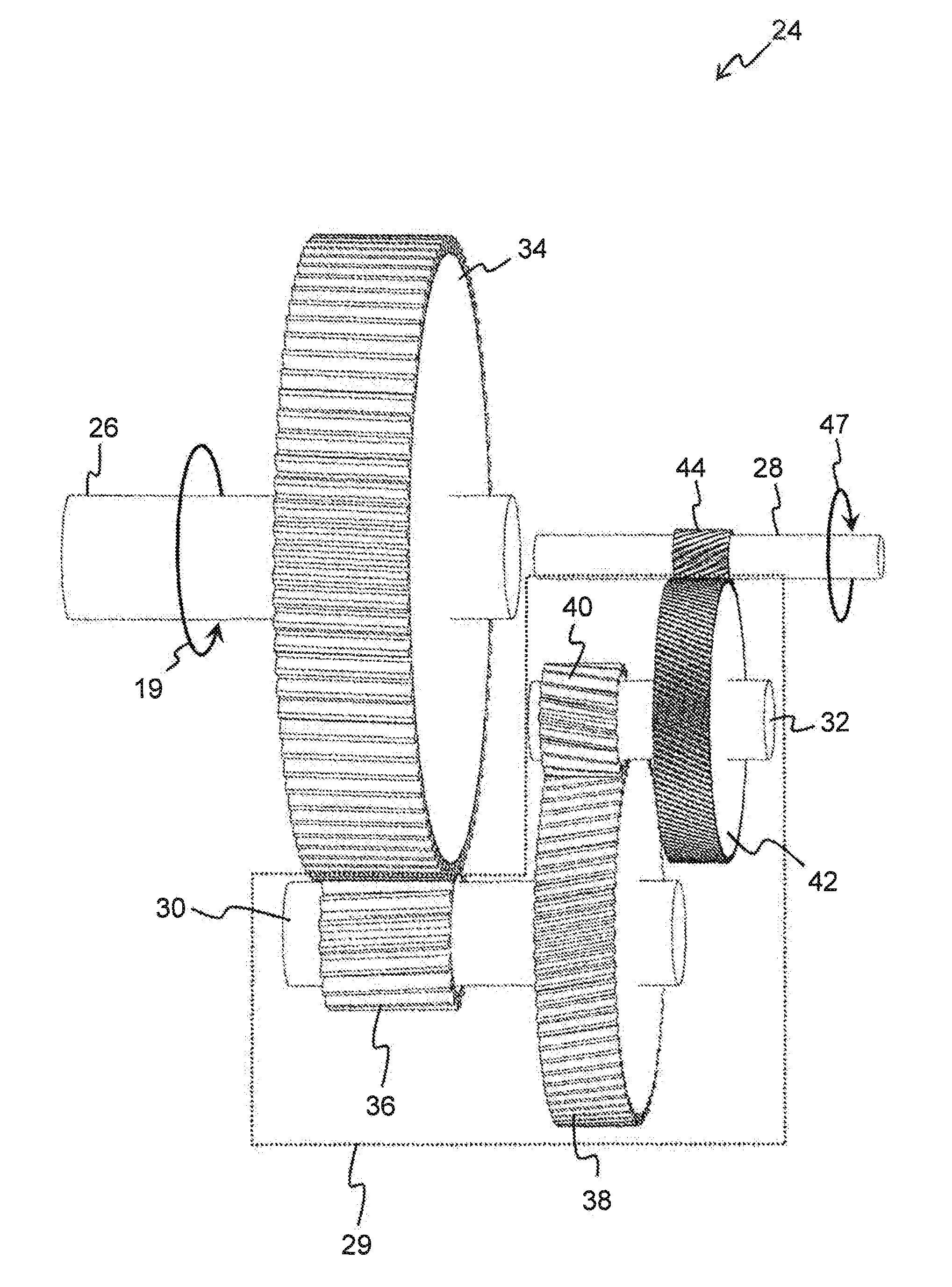
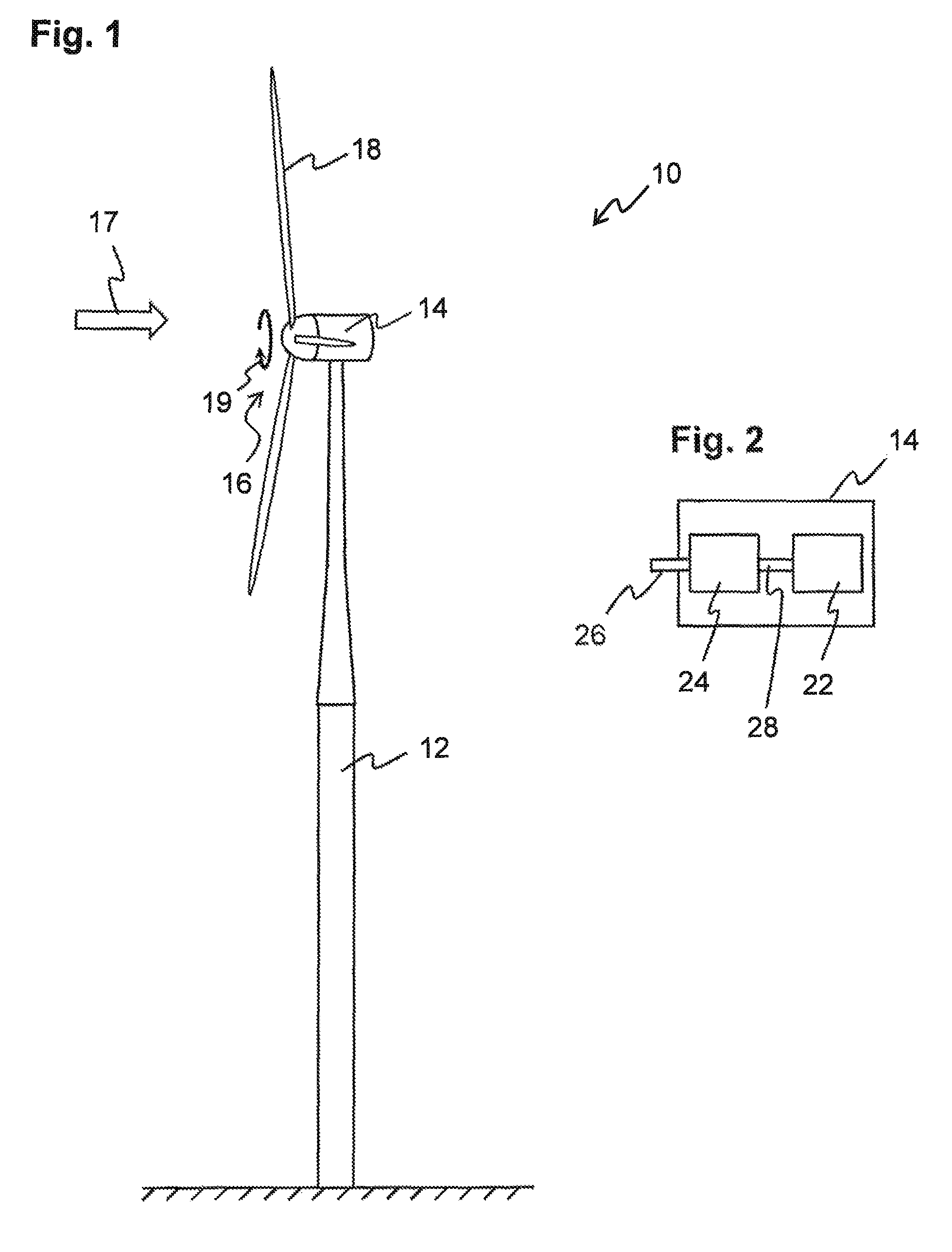
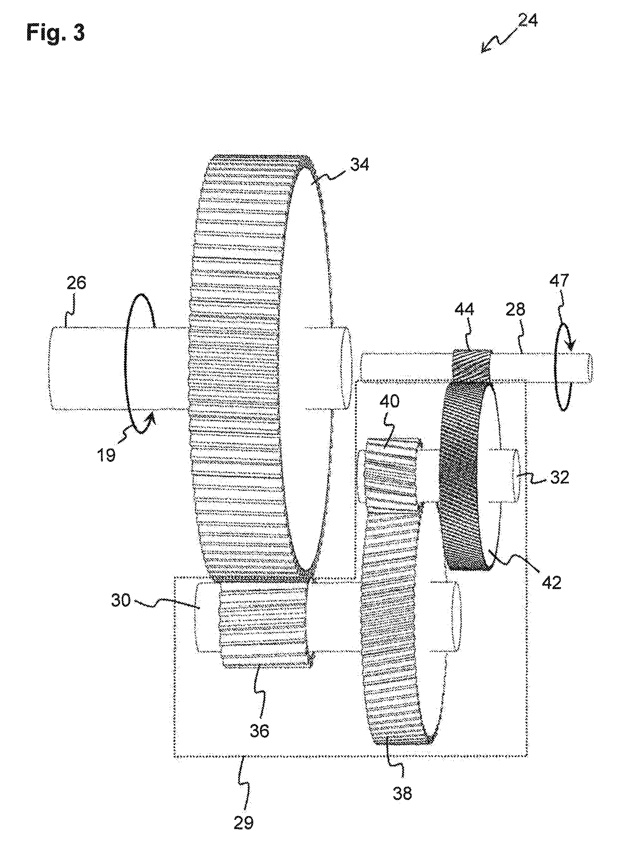
[0059]Wind turbine gear units of prior art, which are generally of the planetary gear type, have a few weaknesses. By way of example, in order to provide a reasonably even distribution of the load between the planet gears, while maintaining reasonably achievable requirements on manufacturing tolerances, at least the sun wheel is generally allowed to self-align in the radial direction. As helical gears are generally used for minimizing wind turbine noise, the shafts of a gear unit are subjected to axial thrust, which is taken up by thrust bearings in the gear unit housing. The rotor shaft typically transmits very high levels of torque to the gear unit; hence, the radial and axial load on the input shaft bearings may, in a typical gear unit, be very high. The high load may cause the gear unit housing to flex or yield, leading to increased axial bearing play and requiring substantial gearing backlash. Such axial play may limit the lifetime of the turbine; hence, the gear unit housing n...


PUM


Abstract

A method of stepping up the speed of a rotary motion from a first speed, supplied to an input shaft (26), to a second speed delivered by an output shaft (28), comprises transmitting said rotary motion from said input shaft (26), via a drive gear (34) of said input shaft (26), the drive gear (34) being helical and having a first helix angle (ψin), to a layshaft arrangement, so as to generate a first axial thrust (F1) of the input shaft (26) in a first axial direction; transmitting said rotary motion from said layshaft arrangement, via a driven gear (44) of said output shaft (28), said driven gear (44) being helical and having a second helix angle (ψout) that is larger than said first helix angle (ψin), to said output shaft (28), so as to generate a second axial thrust (F2) of the output shaft (28) in a second direction, said second direction being substantially opposite to said first direction; and applying said first axial thrust (F1) and said second axial thrust (F2) to the same location of an axially rigid support structure (50), such that said first and second axial thrusts (F1, F2) counter-act and at least partly cancel out in said support structure (50).

Description

CROSS-REFERENCE TO RELATED APPLICATIONS[0001]This application is a 371 U.S. National Stage of International Application No. PCT / SE2011 / 051217, filed on Oct. 12, 2011, which claims priority to Swedish Patent Application No. 1051070-9, filed Oct. 13, 2010, the contents of which are hereby incorporated by reference in their entirety as if fully set forth herein.FIELD OF THE INVENTION[0002]The present invention relates to a method of stepping up the speed of a rotary motion from a first speed, supplied to an input shaft, to a second speed delivered by an output shaft. The present invention further relates to a stationary gear unit comprising an input shaft, and an output shaft substantially parallel with said input shaft, the gear unit being configured for providing a non-unity transmission ratio between said input shaft and said output shaft via a layshaft arrangement.BACKGROUND OF THE INVENTION[0003]The use of wind turbines for generation of electricity is becoming increasingly popula...

Claims


Application Information

Patent Timeline
Patent Type & Authority Patents(United States)
IPC IPC(8): F16H57/021F16H1/20F16H1/22F03D15/00F16H57/02
CPCF16H1/20F03D15/00F16H57/021Y02E10/722Y10T74/19651F05B2260/4031F16H2057/02078Y02E10/72F16H1/26F16H57/00F03D9/255F03D15/10F03D80/70
Inventor BENNSTEDT, NIKLAS
Owner AUTOINVENT TRANSIP
Why Eureka
Try Eureka