

Photographing optical lens assembly
a technology of optical lenses and lens assemblies, applied in the field of photography optical lens assemblies, can solve the problems that the conventional four-lens assembly does not meet the requirements of the high-level photographing lens assembly
- Summary
- Abstract
- Description
- Claims
- Application Information
AI Technical Summary
Benefits of technology
Problems solved by technology
Method used
Image

Examples
first embodiment
The First Embodiment
Embodiment 1
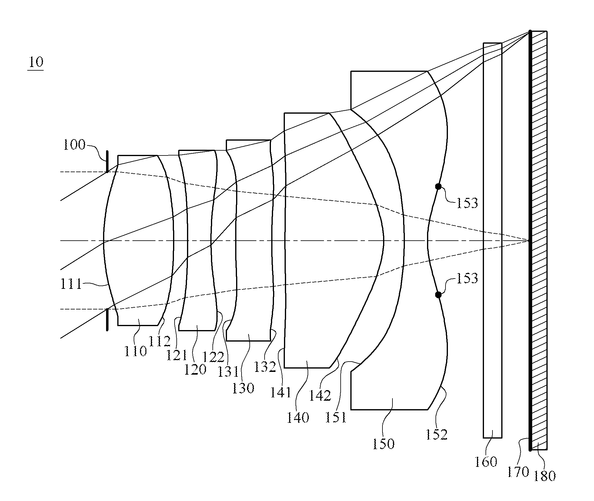
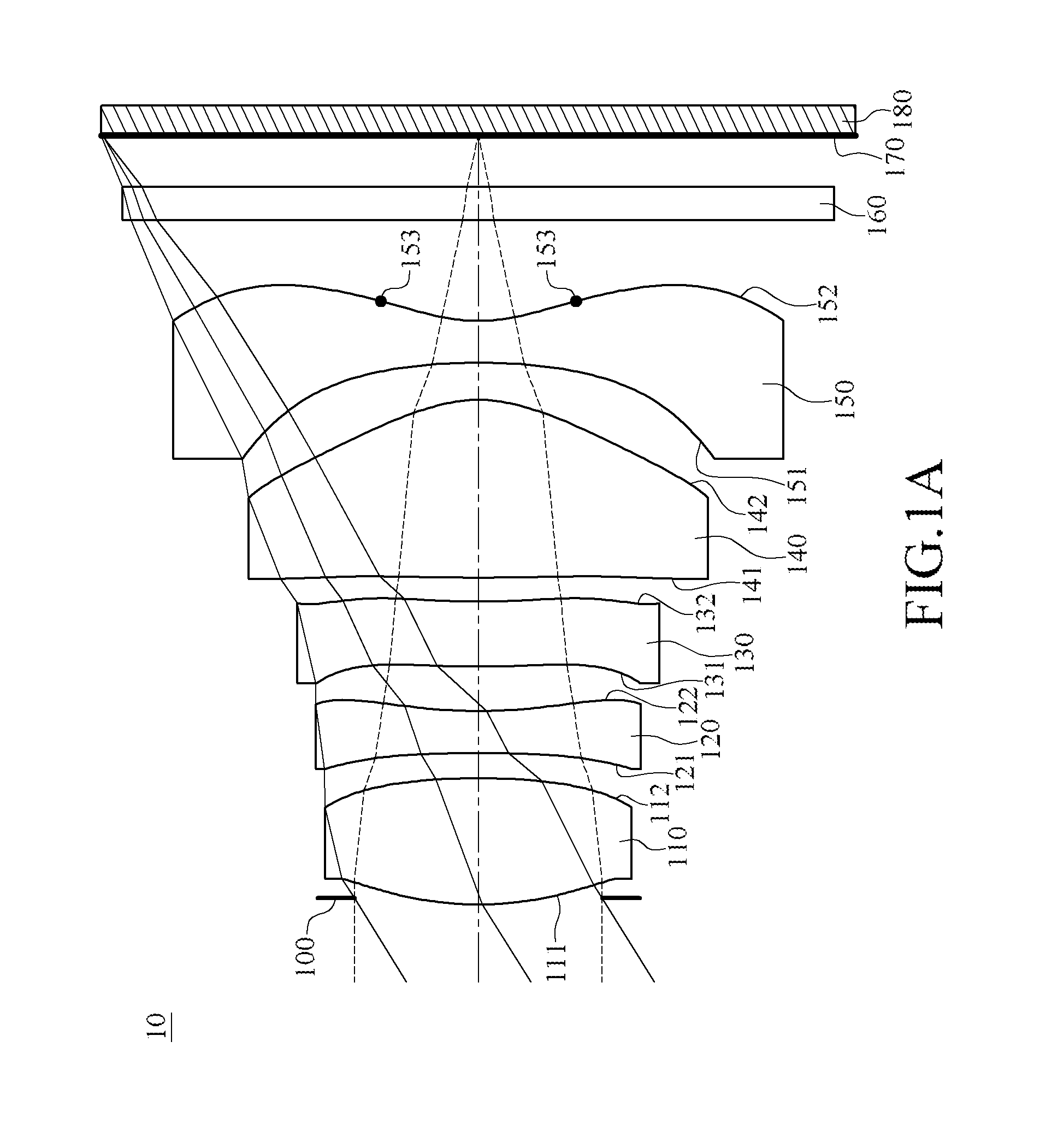
[0075]FIG. 1A is a schematic structural view of the first embodiment of the photographing optical lens assembly. The photographing optical lens assembly 10 comprises, from the object side to the image side along the optical axis (from left to right in FIG. 1A) in sequence, the stop 100, the first lens element 110, the second lens element 120, the third lens element 130, the fourth lens element 140, the fifth lens element 150, the infrared-cut filter 160 and the image sensor 172 disposed on the image plane 170. There are air distances between any two of the first lens element 110, the second lens element 120, the third lens element 130, the fourth lens element 140 and the fifth lens element 150. In this embodiment, the stop 100 is, for example, an aperture stop.
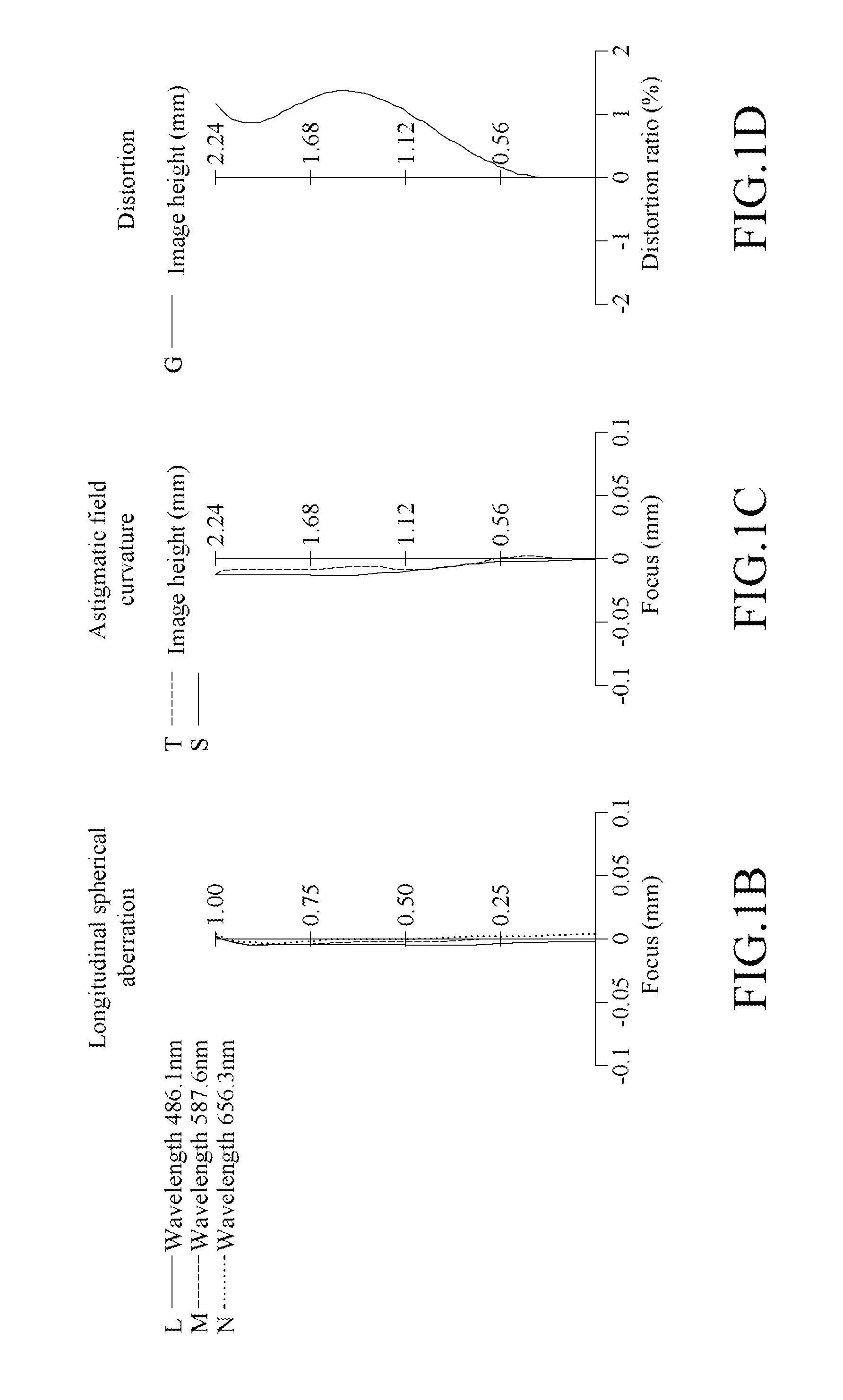
[0076]In this embodiment, light having the reference wavelength of 587.6 nm is projected in the photographing optical lens assembly 10. However, the reference wavelength of the light does not in...
second embodiment
The Second Embodiment
Embodiment 2
[0088]FIG. 2A is a schematic structural view of the second embodiment of the photographing optical lens assembly. The specific implementation and elements of the second embodiment are substantially the same as those in the first embodiment. The element symbols in the second embodiment all begin with “2” which correspond to those in the first embodiment with the same function or structure. For conciseness, only the differences are illustrated below, and the similarities will not be repeated herein.
[0089]In this embodiment, for example, the reference wavelength of the light received by the photographing optical lens assembly 20 is 587.6 nm, but this reference wavelength may be adjusted according to actual requirements, and is not limited to the wavelength value mentioned above.
[0090]In this embodiment, a first lens element 210 with positive refractive power comprises a convex object-side surface 211. A second lens element 220 has negative refractive po...
third embodiment
The Third Embodiment
Embodiment 3
[0097]FIG. 3A is a schematic structural view of the third embodiment of the photographing optical lens assembly. The specific implementation and elements of the third embodiment are substantially the same as those in the first embodiment. The element symbols in the third embodiment all begin with “3” which correspond to those in the first embodiment with the same function or structure. For conciseness, only the differences are illustrated below, and the similarities will not be repeated herein.
[0098]In this embodiment, for example, the reference wavelength of the light received by the photographing optical lens assembly 30 is 587.6 nm, but the reference wavelength may be adjusted according to actual requirements, and is not limited to the wavelength value mentioned above.
[0099]In this embodiment, a first lens element 310 with positive refractive power comprises a convex object-side surface 311. A second lens element 320 has negative refractive power. ...
PUM
 Abstract
Description
Claims
Application Information