Light emitting device and LCD backlight using the same

a technology of light emitting device and backlight, which is applied in the direction of instruments, lighting and heating apparatus, non-linear optics, etc., can solve the problems of inability to continuously use ccfl, limitation in the implementation of images closer to natural colors, and inability to further employ ccfl, etc., to achieve superior white light emitting characteristic, wide color reproduction range, and high luminance

Inactive Publication Date: 2013-02-14
SEOUL SEMICONDUCTOR
View PDF10 Cites 4 Cited by
  • Summary
  • Abstract
  • Description
  • Claims
  • Application Information

AI Technical Summary

Benefits of technology

[0009]The present invention is conceived to solve the aforementioned problems. Accordingly, an object of the present invention is to provide a light emitting device capable of implementing uniform white light and having high luminance and a wide color reproduction range.
[0010]Another object of the present invention is to provide an LCD backlight with uniform light distribution on an LCD as well as low power consumption and high durability using a light emitting device capable of implementing uniform white light and having a wide color reproduction range.
[0026]According to the present invention, a white light emitting device capable of implementing uniform white light and having high luminance and a wide color reproduction range can be manufactured by using blue and red light emitting diode chips and a phosphor that emits green light by means of blue light. In particular, there is an advantage in that a light emitting device of the present invention can be applied to an LCD backlight due to the implementation of uniform light and a superior white light emitting characteristic with a wide color reproduction range.

Problems solved by technology

However, it may be difficult to continuously use the CCFL, because the CCFL cannot be further employed due to the future restriction on the use of mercury.
However, since a color reproduction range which can be expressed when light is transmitted into RGB color filters is considerably narrow in a case where the LCD backlight source module is used as a white light source positioned at the rear of an LCD, there is a limitation in the implementation of images closer to natural colors.
Particularly, since the above color reproduction range is greatly lower than the color reproduction range provided by the National Television System Committee (NTSC), it is difficult to reproduce more realistic colors.
A backlight source using three red, blue and green light emitting diodes can satisfy a considerably wide color reproduction range as compared with an existing CCFL, but since thermal or temporal characteristics of the respective LEDs are different from one another, there are disadvantages in that a color tone is changed depending on a use environment, and particularly, the colors are not uniformly mixed due to the occurrence of uneven colors, or the like.
Further, there are additional disadvantages in that color coordinates vary due to change in the output of each chip depending on an ambient temperature, it is difficult to implement high luminance and a circuit configuration in which the driving of each LED chip is considered is complicated.

Method used


Image

  • Light emitting device and LCD backlight using the same
  • Light emitting device and LCD backlight using the same
  • Light emitting device and LCD backlight using the same

Examples


first embodiment

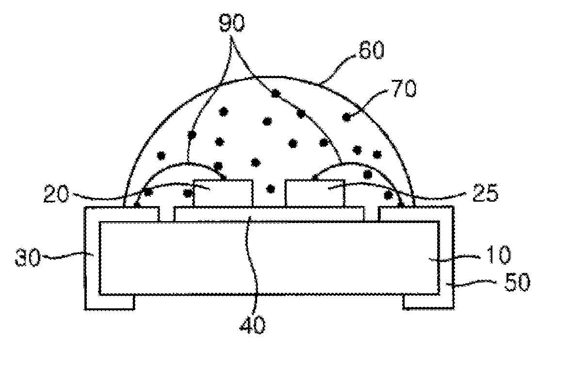
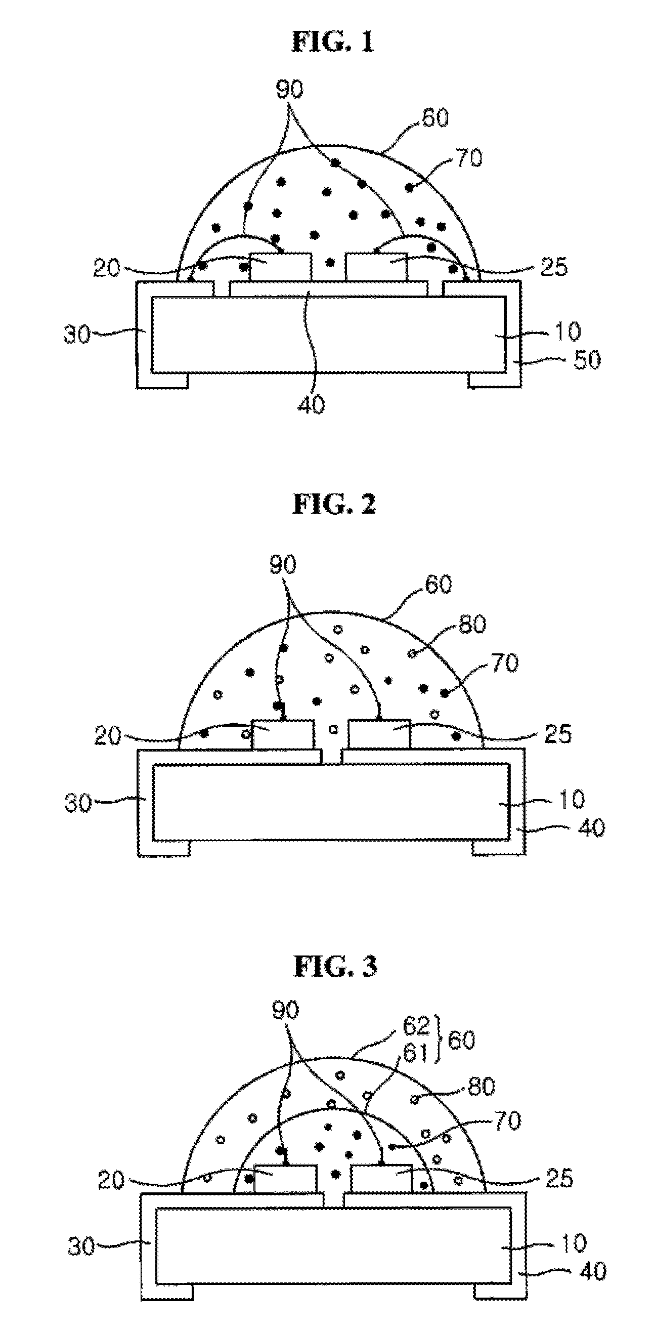
[0065]FIG. 1 is a sectional view showing a light emitting device according to the present invention.

[0066]Referring to this figure, the light emitting device comprises a substrate 10; electrodes 30, 40 and 50 formed on the substrate 10; and LED chips 20 and 25 that emit blue and red light, respectively. A molding member 60 for encapsulating the LED chips 20 and 25 is further formed on top of the substrate, and the aforementioned phosphor 70 is contained in the interior of the molding member 60.

[0067]The substrate 10 may include a reflective portion (not shown) manufactured by forming a predetermined groove in a central region of the substrate 10 and then allowing a sidewall of the groove to be inclined at a predetermined slope. Such a reflective portion is formed such that the reflection of light emitted from the LED chips 20 and 25 can be maximized and emission efficiency can also be enhanced.

[0068]The electrodes of this embodiment include first, second and third electrodes 30, 40 ...

second embodiment

[0075]FIG. 2 is a sectional view showing the light emitting device according to the present invention.

[0076]Referring to this figure, the light emitting device comprises a substrate 10; electrodes 30 and 40 formed on the substrate 10; and LED chips 20 and 25 that emit blue and red light, respectively. A molding member 60 for encapsulating the LED chips 20 and 25 is further formed on top of the substrate 10, and the aforementioned phosphor 70 and a scattering agent 80 are contained in the interior of the molding member 60. The configuration of the light emitting device according to the second embodiment is almost identical with that of the first embodiment, and thus, detailed descriptions overlapping with the first embodiment will be omitted herein.

[0077]The electrodes of the second embodiment are formed to include a first electrode 30, a second electrode 40 and a third electrode (not shown). The LED chips 20 and 25 are mounted on the first and second electrode 30 and 40, respectivel...

third embodiment

[0080]FIG. 3 is a sectional view showing the light emitting device according to the present invention.

[0081]Referring to this figure, the light emitting device comprises a substrate 10; electrodes 30 and 40 formed on the substrate 10; and LED chips 20 and 25 that emit blue and red light, respectively. The configuration of the third embodiment is almost identical with that of the second embodiment, and detailed descriptions overlapping with the second embodiment will be omitted herein. Alternatively, the light emitting device comprises first and second molding members 61 and 62 formed on top of the substrate 10. The phosphors 70 are uniformly distributed in the first molding member 61 to encapsulate the LED chips 20 and 25, and the scattering agents 80 are uniformly distributed in the second molding member 62 to surround the first molding member 61.

[0082]Blue and red light is emitted from the blue and red LED chips 20 and 25, respectively, and a portion of the blue light excites the ...


PUM


Abstract

The present invention provides a light emitting device which comprises blue and red light emitting diode (LED) chips and at least one phosphor for emitting green light by means of light emitted from the blue LED chip, and an LCD backlight including the light emitting device. According to the light emitting device of the present invention, uniform white light can be implemented and both high luminance and wider color reproduction range can also be obtained. Accordingly, an LCD backlight for uniform light distribution on an LCD as well as low power consumption and high durability can be manufactured using the light emitting device.

Description

CROSS-REFERENCE TO RELATED APPLICATIONS[0001]This application is a Continuation of U.S. patent application Ser. No.12 / 088,624, filed on Mar. 28, 2008, which is the National Stage Entry of International Application No. PCT / KR2006 / 003950, filed Sep. 29, 2006 and claims priority from Korean Patent Application No. 10-2006-0021462, filed Mar. 7, 2006, and Korean Patent Application No. 10-2005-0092001, filed Sep. 30, 2005, which are hereby incorporated by reference for all purposes as if fully set forth herein.BACKGROUND[0002]1. Field[0003]The present invention relates a light emitting device and an LCD backlight using the light emitting device. More particularly, the present invention relates to a light emitting device capable of implementing uniform white light and having a wide color reproduction range, and an LCD backlight using the light emitting device.[0004]2. Discussion of the Background[0005]As high-performance portable information processing devices and mobile communication term...

Claims


Application Information

Patent Timeline
Patent Type & Authority Applications(United States)
IPC IPC(8): F21V9/16H01L33/54H01L33/56H01L33/62
CPCG02F1/133603H01L25/0753H01L33/50H01L2224/48091H01L2924/00
Inventor KIM, KYUNG NAMPARK, SANG MIMATSUOKA, TOMIZO
Owner SEOUL SEMICONDUCTOR
Why Eureka
Try Eureka