Sealing assembly for a rolling bearing

a sealing assembly and rolling bearing technology, applied in the direction of mechanical equipment, rotary machine parts, engine components, etc., can solve the problems of difficult to estimate and evaluate the condition of the seal, the seal rings are not always possible to be replaced, and the associated disassembly and downtime costs are extremely high, so as to facilitate the insertion of the seal rings and avoid damage

Inactive Publication Date: 2013-02-14
IMO HOLDING GMBH
View PDF8 Cites 16 Cited by
  • Summary
  • Abstract
  • Description
  • Claims
  • Application Information

AI Technical Summary

Benefits of technology

[0030]It is within the scope of the invention that the cross-sectional shapes of the thrust surfaces for the sealing lips of adjacent seal rings have mutually corresponding transverse curvatures, i.e., that they each have a concave transverse curvature or a convex transverse curvature, or that they each have a flat, i.e. planar, transverse profile with no transverse curvature whatsoever. Such an at least structurally identical transverse curvature—even if the radius of transverse curvature changes—also facilitates the insertion of the seal rings.
[0031]Further advantages are obtained if the cross-sectional shapes of the thrust surfaces for the sealing lips of adjacent seal rings have the same axial inclination, particularly are in mutual axial alignment. This feature is also intended to make the handling of the seal ring(s) as problem-free as possible.
[0032]Since the sealing lips of two adjacent seal rings bear or thrust against a common cylindrical surface region having a constant diameter, the seal rings need not be stretched or otherwise deformed during insertion and thus are not at risk of being damaged.
[0033]Finally, it is within the teaching of the invention that an outer seal is provided with a dust lip. The risk of ingress of dust or other particles can be effectively countered in this way. The element in question can be an additional seal ring, which may have a different cross section from the other seal rings of the particular gap seal.

Problems solved by technology

Due to the compact construction of wind power installations, it is not always possible to replace these seal rings once they are installed.
The associated disassembly and downtime costs are extremely high.
In addition, this often very poor accessibility makes it difficult to estimate and evaluate the condition of a seal.
Since a rotor bearing of this kind, which can easily weigh several tons, still is, or will be, connected to the generator, and perhaps to other parts of the adjacent structure, the possibility cannot always be ruled out that dirt may get into the vicinity of the seal, for example, in the course of installation, maintenance or repair work, with consequent damage to the sealing lip and thus impairment of the overall sealing effect.

Method used


Image

  • Sealing assembly for a rolling bearing

Examples


Embodiment Construction

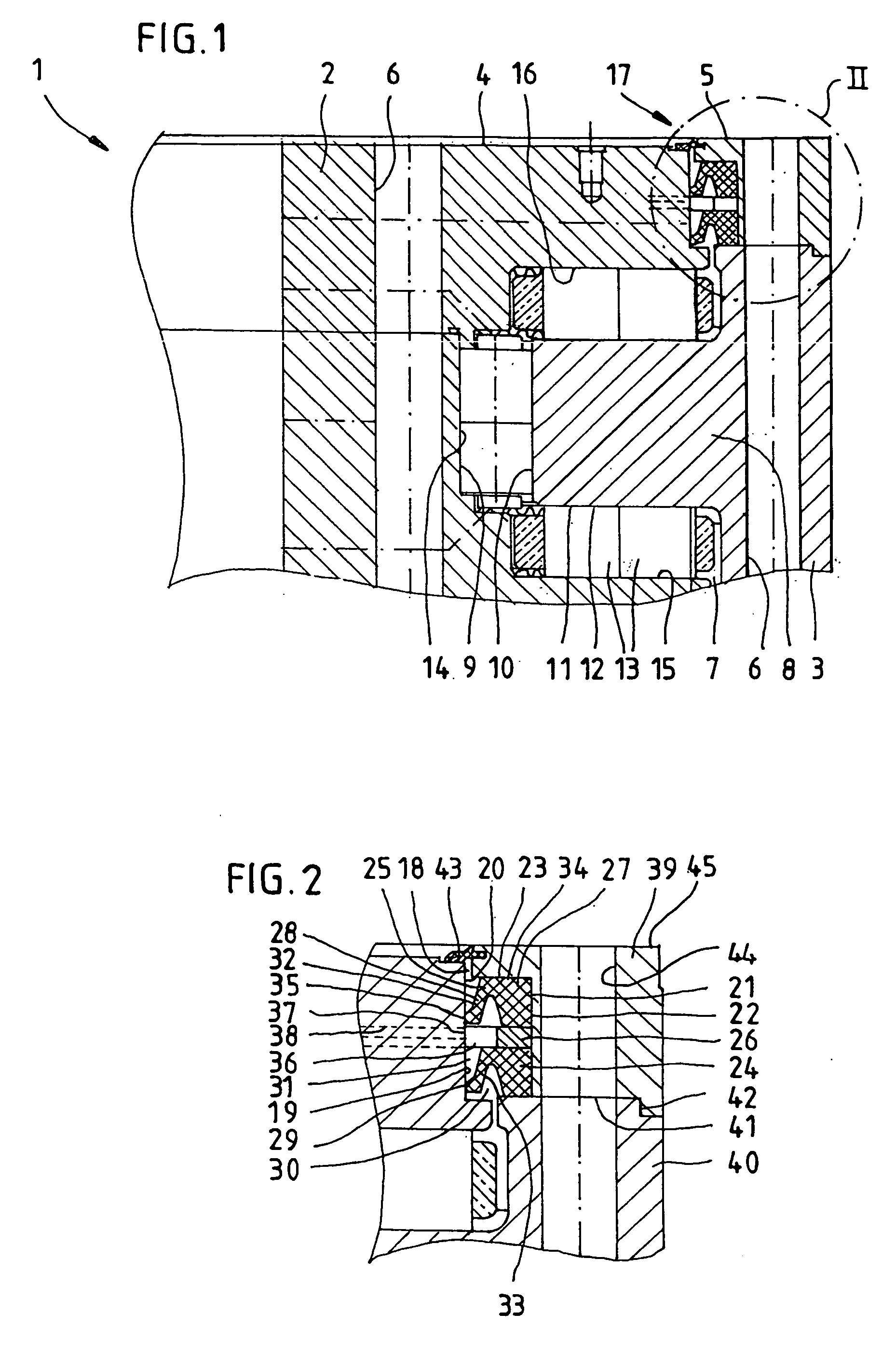
[0037]The drawings illustrate an example of a preferred embodiment of the sealing principle according to the invention. It depicts a rolling bearing 1 that is preferably intended for use in a wind power installation, particularly as a rotor bearing or main bearing.

[0038]Apparent in the drawing are two mutually concentric bearing rings, an inner ring 2 of planar, circular shape and, engaged around the outside thereof, an outer ring 3 of corresponding geometry. Each of the two rings 2, 3 preferably has planar end faces 4, 5, which can serve as connection surfaces for connection to a foundation or to an installation part or machine part. Provided for this purpose, in at least one end face 4, 5 per bearing ring 2, 3, is a plurality of coronally arranged fastening means, particularly fastening bores 6, whose longitudinal axes preferably extend perpendicularly to the respective end face 4, 5 and which are intended for machine screws, (threaded) bolts, or the like, to be passed through or ...


PUM


Abstract

The invention relates to a sealing assembly for a rolling bearing having two mutually concentric rings spaced apart from each other by a fully circumferential gap in which one or more rows of revolving rolling elements are disposed, such that the two rings are rotatable relative to each other about their common axis, wherein the gap is sealed in the region of at least one of its two mouths, and wherein provided in the region of a gap seal are at least two seal rings, each having at least one sealing lip and an anchoring region on a surface region of the particular seal ring that faces away from the sealing lip, the seal rings being fixed to the same rolling bearing ring, whereas their respective sealing lips bear against the other rolling bearing ring, specifically against surface regions having identical or similar cross section.

Description

BACKGROUND OF THE INVENTION[0001]1. Field of the Invention[0002]The invention relates to a sealing assembly for a rotary joint, particularly for a rolling bearing comprising two mutually concentric rings spaced apart from each other by a circumferential gap in which one or more rows of revolving rolling elements are disposed, such that the two rings are rotatable relative to each other about their common axis, and wherein the gap is sealed in the region of at least one of its two mouths.[0003]2. Description of the Prior Art[0004]The field of application for rotary joints in general, and for rolling bearings in particular, is boundless. Rotary joints of the type of the invention, particularly rolling bearings, are commonly lubricated with grease, less often with oil. The lubricant is retained in the region of the (rolling) bearing by seals, preferably disposed on both sides. The seals are frequently in the form of individual shaft seal rings, which are fixed with additional retaining...

Claims


Application Information

Patent Timeline
Patent Type & Authority Applications(United States)
IPC IPC(8): F16C33/78
CPCF16C2300/14F16C33/7896F16C19/381F16C2360/31
Inventor RUSS, ERICHFRANK, HUBERTUS
Owner IMO HOLDING GMBH
Why Eureka
Try Eureka