

Image forming apparatus
- Summary
- Abstract
- Description
- Claims
- Application Information
AI Technical Summary
Benefits of technology
Problems solved by technology
Method used
Image

Examples
Embodiment Construction
[0030]Various exemplary embodiments, features, and aspects of the invention will be described in detail below with reference to the drawings.
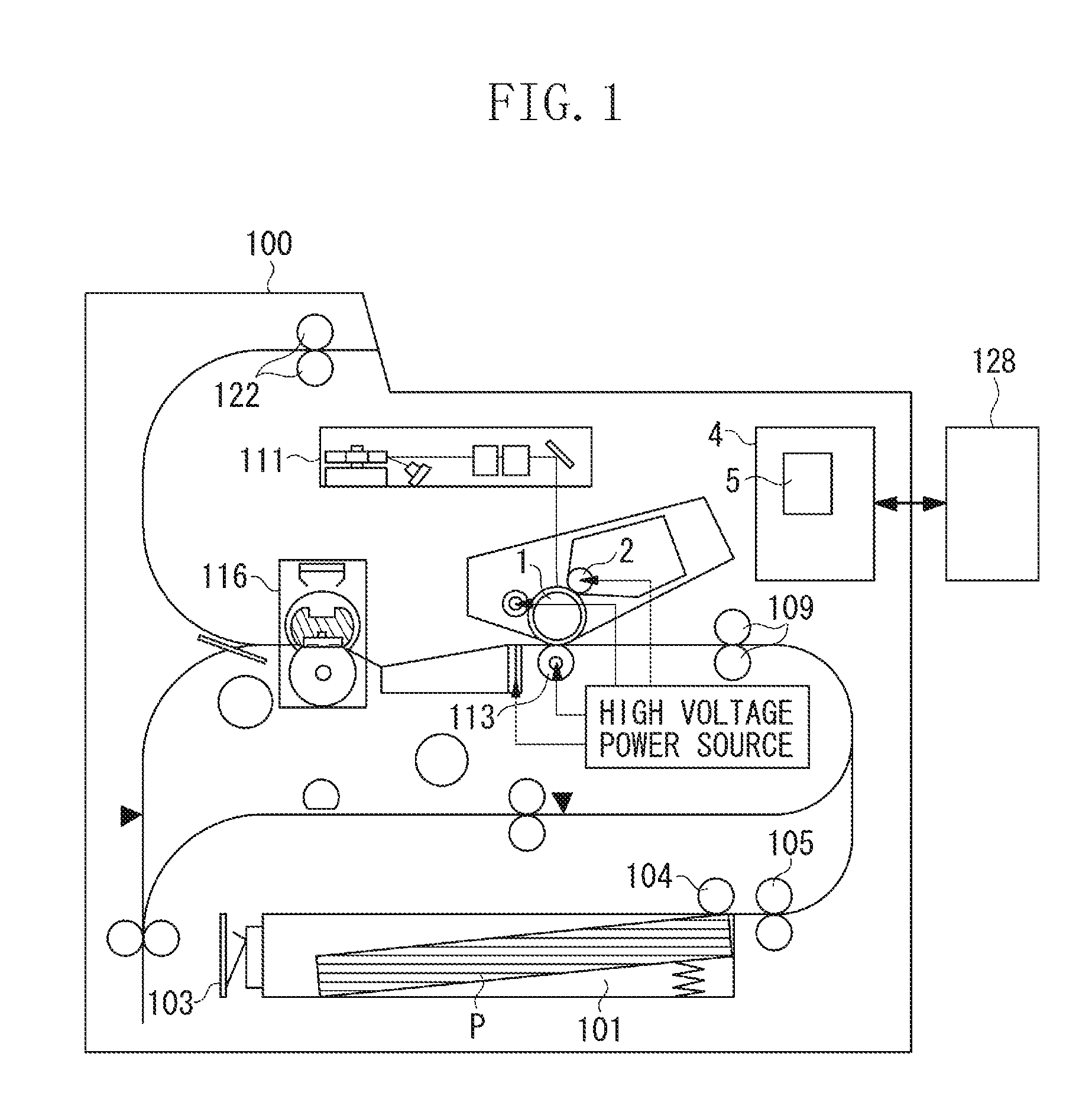
[0031]In the following, a first exemplary embodiment of the present invention will be described with reference to the drawings. FIG. 1 is a schematic diagram illustrating a laser beam printer 100 according to the first exemplary embodiment. A recording material P is accommodated in a cassette 101, and the sheet size of the recording material P is detected by a sheet size detection sensor 103 provided within the cassette 101. The recording material P, which is drawn out by a pickup roller 104, is conveyed to a registration roller pair 109 by a sheet feeding roller 105. A laser scanner unit 111 performs scanning on a photosensitive drum 1 based on image information from a video controller 128 to forma latent image on the photosensitive drum 1. The latent image formed on the photosensitive drum 1 is developed by a developing roller 2 to be turned ...
PUM
 Abstract
Description
Claims
Application Information