Micromixer heat shield

a micro-mixer and heat shield technology, applied in the ignition of the turbine/propulsion engine, engine starters, lighting and heating apparatus, etc., can solve the problems of premature failure of such components

Inactive Publication Date: 2013-02-21
GENERAL ELECTRIC CO
View PDF9 Cites 18 Cited by
  • Summary
  • Abstract
  • Description
  • Claims
  • Application Information

AI Technical Summary

Problems solved by technology

Over cycles, such thermal gradients and/or thermal stresses may limit the useful life o

Method used


Image

  • Micromixer heat shield
  • Micromixer heat shield
  • Micromixer heat shield

Examples


Embodiment Construction

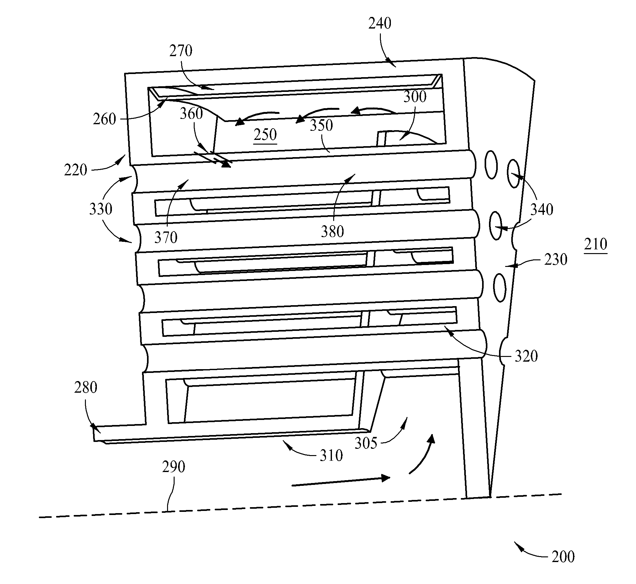
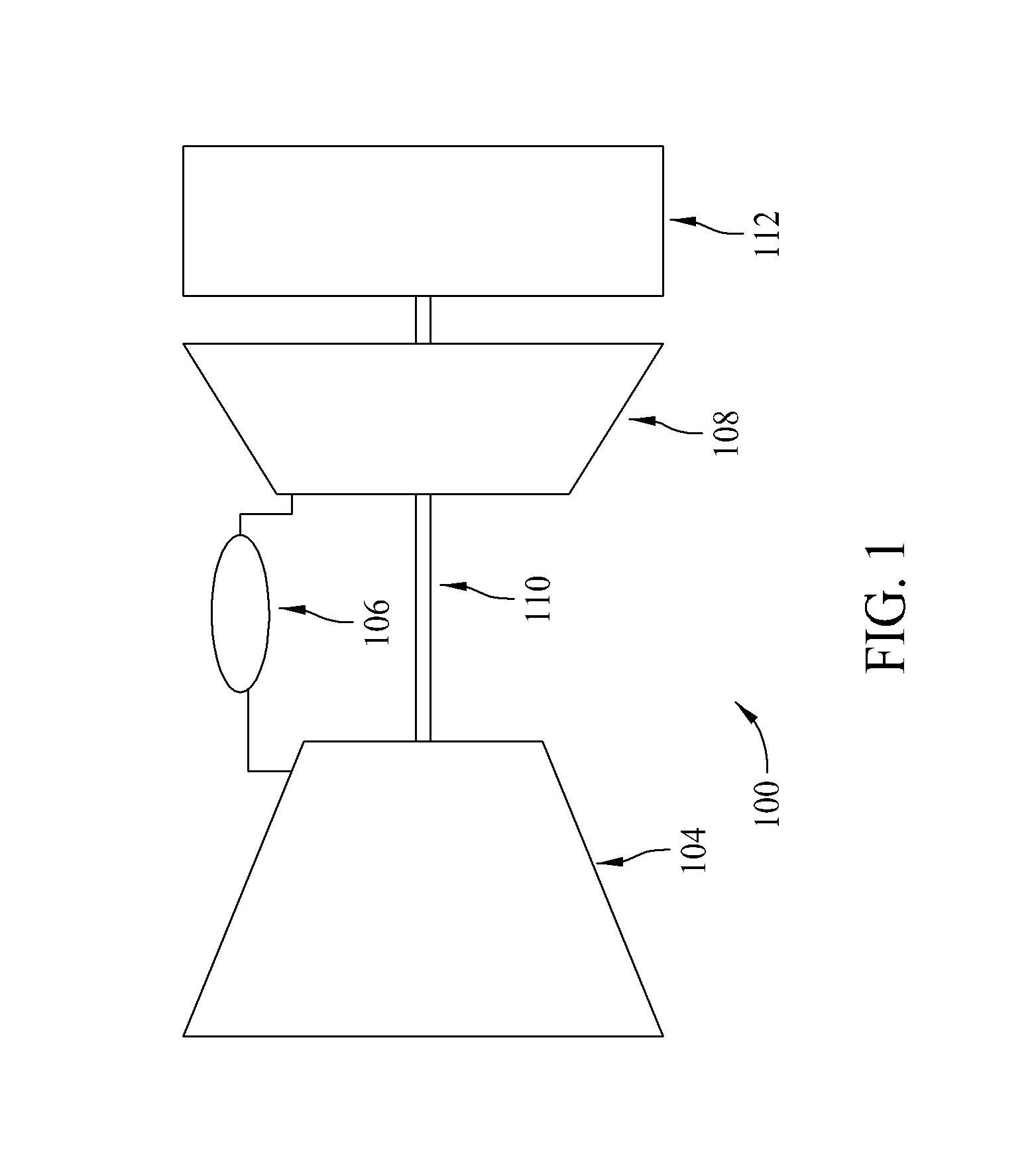
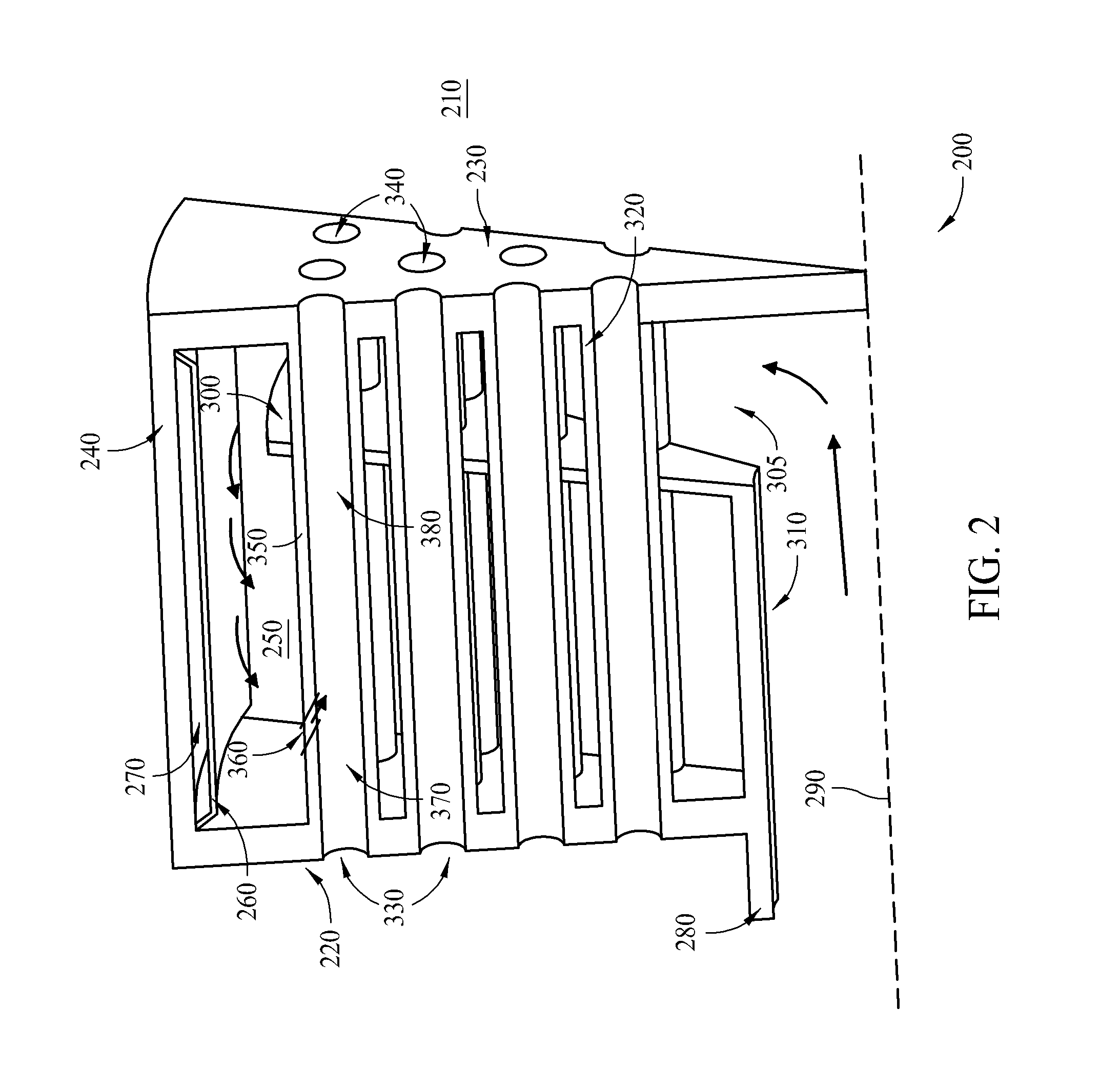
[0010]The subject matter described herein relates generally to turbine systems and more particularly to a micromixer that may be used with a turbine system. In one embodiment, a fuel nozzle includes a forward face, an aft face downstream from the forward face, a plurality of mixing tubes that extend between the forward and aft faces, an outer sleeve positioned radially outward of the plurality of mixing tubes, a heat shield positioned radially inward of the outer sleeve, and a baffle plate positioned between the forward and aft faces. In such an embodiment, the fuel nozzle channels fuel downstream through a center supply tube towards a space defined between the baffle plate and the aft face. The fuel is channeled radially outward through the space defined between the baffle plate and the aft face, and then the fuel is channeled upstream towards an injection opening defined in a mixing tube. The fuel is channeled through the injection opening, and then the fuel is mixed with air chan...


PUM


Abstract

A combustor includes a combustor wall defining a combustion zone and a fuel nozzle. The fuel nozzle includes a forward face, an aft face downstream from the forward face and adjacent to the combustion zone, a plurality of mixing tubes extending between the forward face and the aft face, an outer sleeve positioned radially outward of the plurality of mixing tubes, a heat shield positioned radially inward of the outer sleeve, and a baffle plate between the forward face and the aft face. At least one of the plurality of mixing tubes includes a sidewall that includes an injection opening defined therethrough. The baffle plate is oriented to channel fuel between the plurality of mixing tubes and between the baffle plate and the aft face prior to the fuel being channeled through the injection opening.

Description

BACKGROUND[0001]The present disclosure relates generally to a turbine system and more particularly to a micromixer fuel nozzle that may be used with a turbine system.[0002]Some known turbine systems include at least one combustor assembly that mixes compressed air with fuel and ignites the fuel-air mixture to generate combustion gases within a combustion zone defined in the combustor assembly. More specifically, at least some known combustor assemblies use a micromixer that includes an outer sleeve that is oriented to channel air and / or fuel towards the combustion zone and an aft face that is positioned adjacent to the combustion zone. As a result, the aft face is exposed to the relatively high temperatures generated within the combustion zone.[0003]At least some known micromixers channel air and / or fuel towards the combustion zone at a relatively high velocity. Channeling the air and / or fuel at such a velocity ensures that energy losses within the air and / or fuel are minimized, but...

Claims


Application Information

Patent Timeline
IPC IPC(8): F02C7/26B05B15/00F02C7/22
CPCF23R3/286F23R3/48F23R2900/00002
Inventor BARKER, CARL ROBERTJOHNSON, THOMAS EDWARD
Owner GENERAL ELECTRIC CO
Why Eureka
Try Eureka