Light-emitting diode structure

a technology of led modules and light-emitting diodes, which is applied in the direction of basic electric elements, electrical equipment, semiconductor devices, etc., can solve the problems of reducing the efficacy of the whole led module, affecting the light efficiency and the life of fluorescent powder coated on the chips, and increasing the manufacturing cost. , to achieve the effect of upgrading light efficiency and light efficiency

Inactive Publication Date: 2013-02-21
WANG RICHARD TA CHUNG
View PDF2 Cites 14 Cited by
  • Summary
  • Abstract
  • Description
  • Claims
  • Application Information

AI Technical Summary

Benefits of technology

[0008]A primary object of the present invention is to provide an LED structure that provides upgraded light efficiency.
[0009]Another object of the present invention is to provide an LED structure that enables quick change of LED color temperature or LED beam angle.
[0010]A further object of the present invention is to provide an LED structure that eliminates the problem of luminous flux attenuation caused by fluorescent powder constantly working under high temperature.
[0011]To achieve the above and other objects, the LED structure according to the present invention includes a substrate having a recess formed on one side thereof and at least one retaining section provided on along a peripheral wall thereof; a plurality of LED chips arranged in the recess of the substrate; a first colloid located in the recess of the substrate to cover the LED chips; a second colloid located to one side of the first colloid opposite to the substrate; and a lens having at least one catching section provided on along a peripheral wall thereof for correspondingly engaging with the at least one retaining section on the substrate. The lens is connected to the substrate to form a unitary body through engagement of the catching section with the retaining section, and closes the LED chips, the first colloid and the second colloid in between the lens and the substrate. With the second colloid located between the lens and the first colloid, and the catching section detachably engaged with the retaining section, the LED structure can provide upgraded light efficiency and enables quick change of LED color temperature or LED beam angle.

Problems solved by technology

Meanwhile, the temperature at a central hot spot of the LED structure would adversely affect the lighting efficiency and the life of the fluorescent powder coated on the chips.
Although this technique enables lowered temperature at the fluorescent powder layer, the luminous efficacy of the whole LED module is reduced and the manufacturing cost is increased, and LED lamps produced with this technique also have reduced lighting efficiency.
In brief, the conventional LED structures have the following disadvantages: (1) poor lighting efficiency; and (2) increased manufacturing cost.

Method used


Image

  • Light-emitting diode structure
  • Light-emitting diode structure
  • Light-emitting diode structure

Examples


Embodiment Construction

[0023]The present invention will now be described with some preferred embodiments thereof and with reference to the accompanying drawings. For the purpose of easy to understand, elements that are the same in the preferred embodiments are denoted by the same reference numerals.

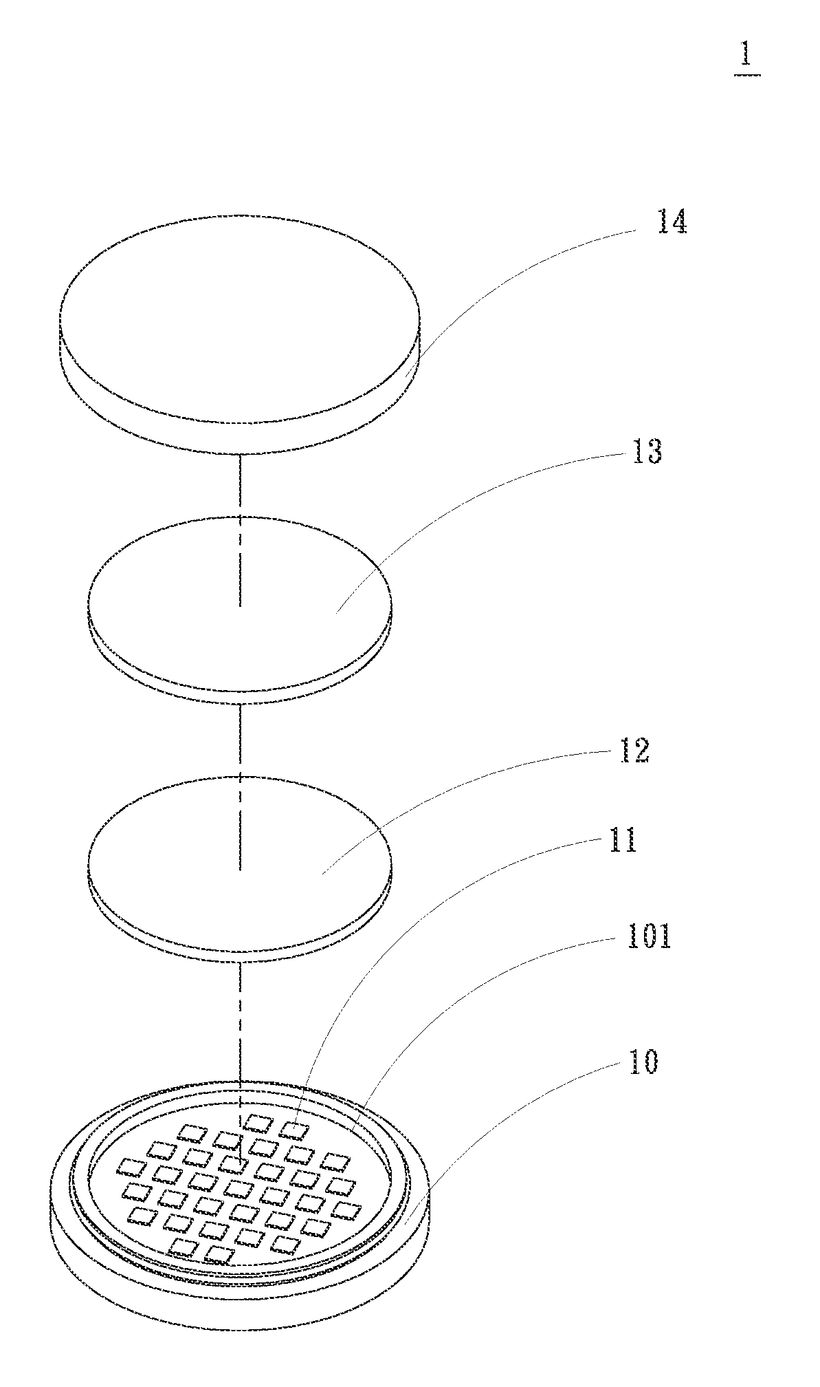
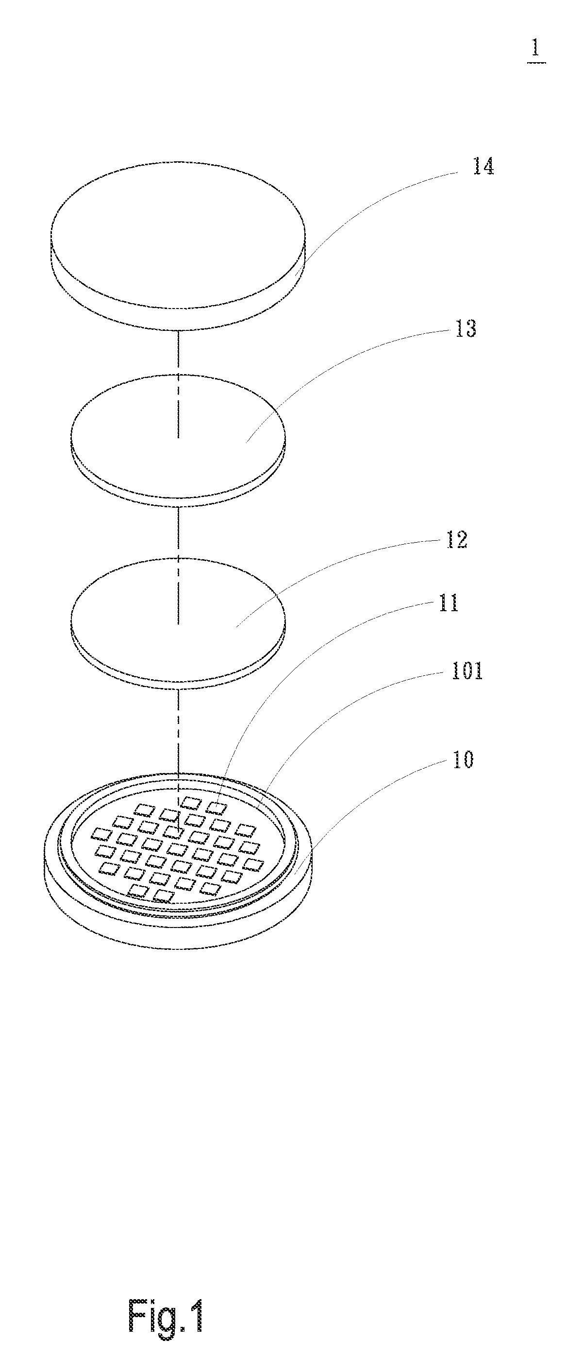
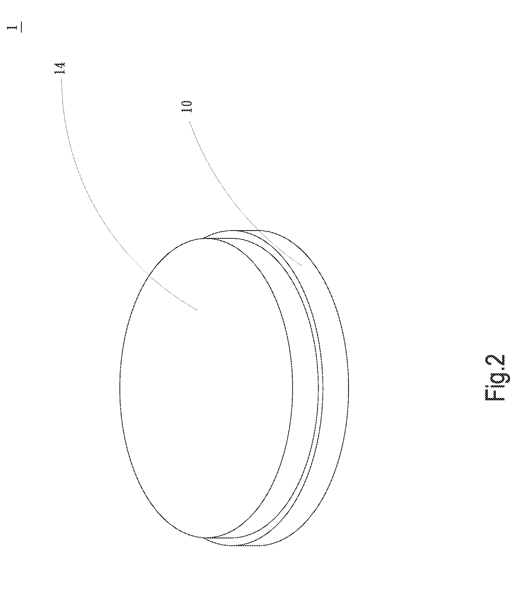
[0024]Please refer to FIGS. 1 and 2 that are exploded and assembled perspective views, respectively, of an LED structure 1 according to a first preferred embodiment of the present invention, and to FIG. 3 that is a sectional view of FIG. 2. As shown, the LED structure 1 in the first preferred embodiment includes a substrate 10, a plurality of light-emitting diode (LED) chips 11, a first colloid 12, a second colloid 13, and a lens 14.

[0025]The substrate 10 is formed on one side with a recess 101, and is provided on along a peripheral wall with at least one retaining section 102. In the illustrated first embodiment, the retaining section 102 is extended along the peripheral wall of the substrate 10. The LED chips...


PUM


Abstract

A light-emitting diode (LED) structure includes a substrate, a plurality of LED chips, a first colloid, a second colloid, and a lens. The substrate is provided with at least one retaining section, and the LED chips are mounted on the substrate and covered by the first colloid. The second colloid is located to one side of the first colloid opposite to the substrate. The lens is provided with at least one catching section correspondingly engaged with the at least one retaining section, so that the lens is connected to the substrate to form a unitary body through engagement of the catching section with the retaining section and closes the LED chips, the first colloid and the second colloid in between the lens and the substrate. With these arrangements, the LED structure can have upgraded lighting efficiency and allows quick change of LED color temperature or LED beam angle.

Description

FIELD OF THE INVENTION[0001]The present invention relates to a light-emitting diode (LED) structure, and more particularly to an LED structure including a substrate and a lens that can be quickly connected to each other through engagement of a retaining section and a catching section to enclose LED chips and colloid layers in between the substrate and the lens, so as to enable upgraded LED lighting efficiency and quick change of LED color temperature or LED beam angle.BACKGROUND OF THE INVENTION[0002]Due to the rapid development in the recent light-emitting diode (LED) illuminating industry, the currently available LEDs can now have higher brightness and power, longer service life, lower power consumption, and faster response than the conventional energy-saving bulbs to thereby gradually replace the latter. Among others, high-power LEDs have been widely used on street lamps, scenery lighting, linear wall washer lights, interior illumination, and many other different lighting applica...

Claims


Application Information

Patent Timeline
Patent Type & Authority Applications(United States)
IPC IPC(8): H01L33/58
CPCH01L25/0753H01L33/507H01L33/58H01L33/648H01L2924/0002
Inventor WANG, RICHARD TA-CHUNGLI, SHANG-BINXU, ZHENG-FEIZOU, JUN
Owner WANG RICHARD TA CHUNG
Why Eureka
Try Eureka