
Liquid sealed vibration isolating device

Active Publication Date: 2013-02-21
YAMASHITA RUBBER CO LTD
View PDF6 Cites 12 Cited by
  • Summary
  • Abstract
  • Description
  • Claims
  • Application Information

AI Technical Summary

Benefits of technology

The present invention relates to hydraulic damping devices for controlling the movement of hydraulic liquid in a hydraulic system. The invention provides a device that can easily open and close a second passage for communication with a secondary liquid chamber, and can perform multiple functions such as changing the spring in response to the displacement and making variable the internal pressure absorption capacity against the internal pressure change of the primary liquid chamber. The device includes an elastic diaphragm and a stopper leg portion that can easily function as an opening and closing valve for the second passage, and can have the multifunctional capability. The invention also provides a support wall with an inclined portion that changes in compression amount due to press reaction force from the inclined portion in proportion to the size of displacement of the elastic diaphragm, and the position in which a gap is created between the inclined portion and the stopper leg portion can be used as the open position of the stopper leg portion. The invention also provides a pressing surface that can increase the contact with the support wall and restrain the deformation of the stopper leg portion to realize the high damping.

Problems solved by technology

Then, there occurs the cavitation phenomenon which produces a noise when the bubbles burst.

Method used


Image

  • Liquid sealed vibration isolating device
  • Liquid sealed vibration isolating device
  • Liquid sealed vibration isolating device

Examples


first embodiment

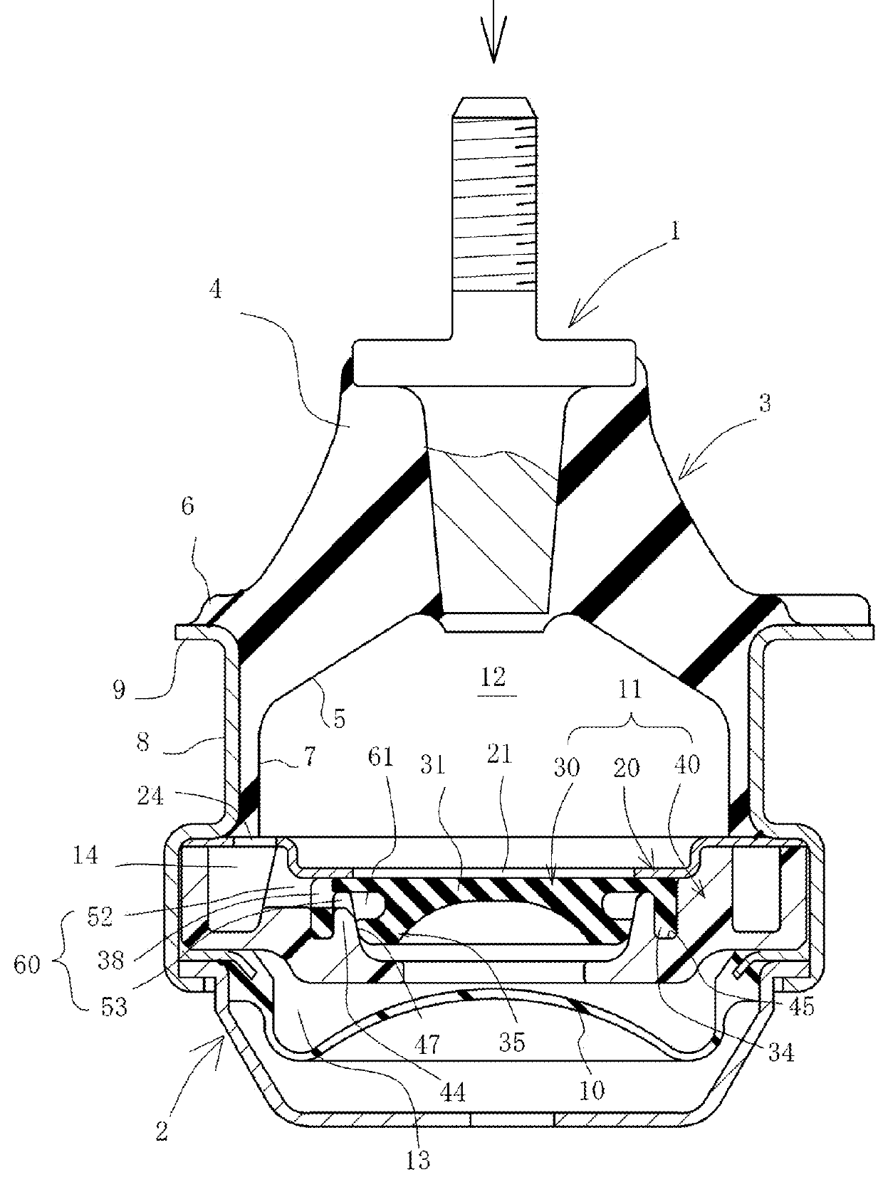
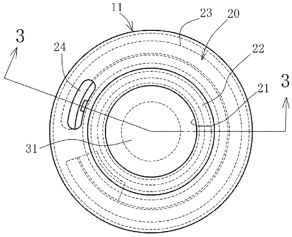
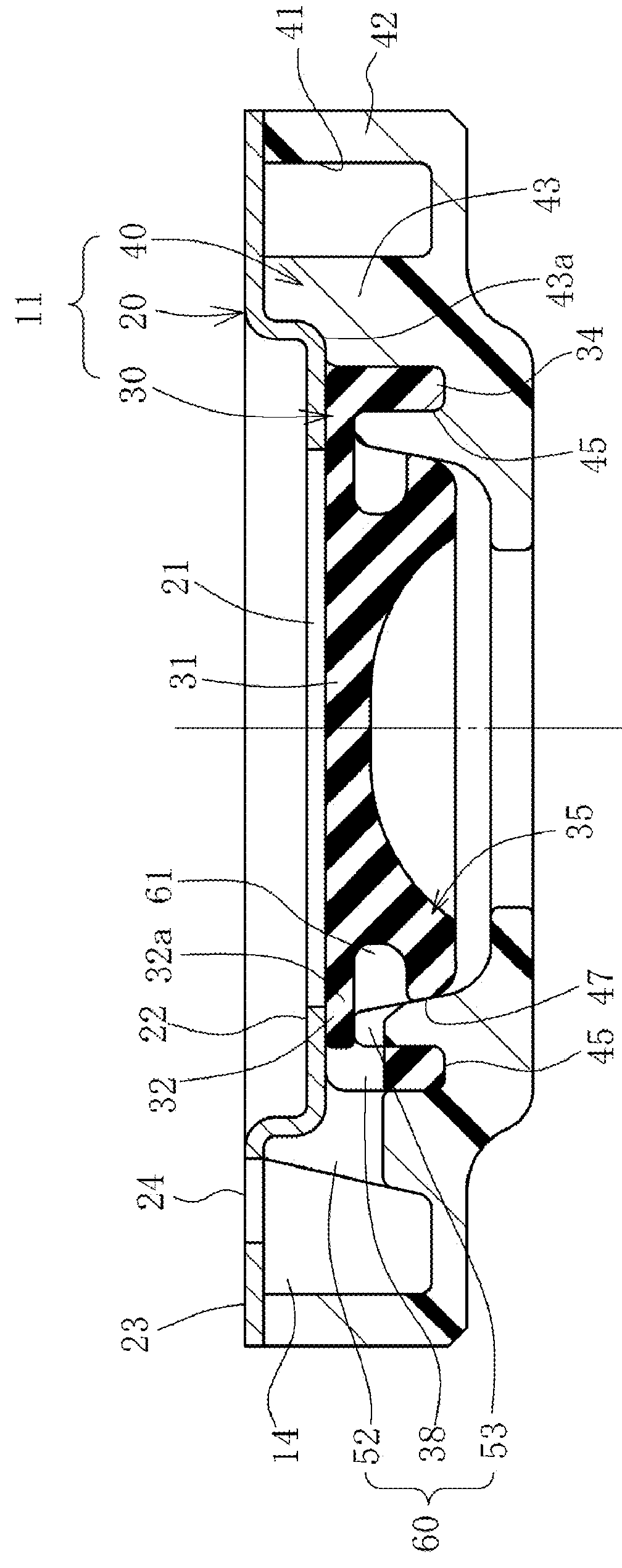
[0066]Hereinafter, embodiments of the present invention configured as an engine mount for a motor vehicle will be described with reference to the accompanying drawings. At first, a first embodiment will be described with reference to FIGS. 1 through 8. FIG. 1 is a cross sectional view taken along a central axis (parallel to the direction of an arrow Z) of the engine mount. FIG. 2 is a plan view of a partition member. FIG. 3 is a cross sectional view taken along line 3-3 of FIG. 2. FIG. 4 is an exploded perspective view of the partition member. FIG. 5 is an exploded cross sectional view of the partition member. FIGS. 6 through 8 are explanatory views of the operation. In the description hereunder, an upper and lower sides of a liquid sealed vibration isolating device and of each component element thereof are set on the basis of the state illustrated in FIG. 1, wherein an upper side designates a primary liquid chamber side and a lower side designates a secondary liquid chamber side wi...

second embodiment

[0141]Next, the operation of the second embodiment will be described. When the vibration is inputted and the internal pressure of the primary liquid chamber 112 is fluctuated by the elastic deformation of the elastic main body 103, the elastic diaphragm portion 131 is elastically deformed to absorb the fluctuation of the internal pressure. Then, as shown in FIG. 15, the stopper leg portion 135 is deformed together with the elastic diaphragm portion 131, and the forward end of the pressing portion 37 is pressed on the inclined portion 157 in the direction substantially orthogonal to the inclined surface, so that the seal rib 137b is compressed so as to closely contact the inclined portion 157.

[0142]In this condition, at the time of the normal condition in which the amplitude of the input vibration is comparatively small, the pressing portion 137 slides up and down on the inclined portion 157 in the position below the lower end of the taper shaped concave 155, and the elastic diaphrag...


PUM


Abstract

A partition member for partitioning a primary liquid chamber and a secondary liquid chamber is provided with a damping orifice passage and an elastic partition member. A stopper leg portion is integrally formed with and projects from a lower wall of an elastic diaphragm portion provided in a central region of the elastic partition member 30 so as to be pressed on a pressed surface of a support wall of a frame member. A third liquid chamber is defined by the support wall, the elastic partition member and the stopper leg portion and is opened in the vicinity of a primary liquid chamber side opening of the damping orifice passage through a relief passage. The pressed surface is increased in diameter as it goes upward.

Description

BACKGROUND OF THE INVENTION[0001]1. Field of the Invention[0002]The present invention relates to a liquid sealed vibration isolating device for use in an engine mount for a motor vehicle, and more particularly, to the device which allows a hydraulic liquid passage such as a relief passage for restraining a cavitation phenomenon, to be opened and closed by utilizing the existing structure.[0003]Further, the present invention relates particularly to the device which comprises an elastic diaphragm portion for absorbing internal pressure of a primary liquid chamber, and a stopper leg portion being integrally provided on and projecting from the elastic diaphragm portion, wherein deformation control of the elastic diaphragm portion is performed by the stopper leg portion.[0004]2. Description of the Related Art[0005]As a liquid sealed vibration isolating device of this type there is publicly known the device that a partition member for separating the primary liquid chamber and a secondary ...

Claims


Application Information

Patent Timeline
IPC IPC(8): F16F13/10
CPCF16F13/105
Inventor SATORI, KAZUTOSHIHIRANO, YUKINOBU
Owner YAMASHITA RUBBER CO LTD
Features
  • Generate Ideas
  • Intellectual Property
  • Life Sciences
  • Materials
  • Tech Scout
  • Unparalleled Data Quality
  • Higher Quality Content
  • 60% Fewer Hallucinations
Learn More