Bumper structure

a bumper and structure technology, applied in the field of vehicle bumper structures, can solve the problems of reduced impact absorption capacity of vehicles, insufficient vertical overlap amount, etc., and achieve the effect of simple structure and increased vertical overlap amoun

Active Publication Date: 2013-02-21
TOYOTA JIDOSHA KK
View PDF9 Cites 8 Cited by
  • Summary
  • Abstract
  • Description
  • Claims
  • Application Information

AI Technical Summary

Benefits of technology

[0007]The invention provides a bumper structure that increases the vertical overlap amount but is simple in structure.

Problems solved by technology

In the case of a vehicle that is relatively small in height, the vertical level of each bumper is low as compared to the vertical level of the barrier, and therefore the vertical overlap amount is not sufficient.
In this case, because the vertical overlap amount is not sufficient, the vehicle may get into the lower side of the barrier, that is, so-called underride may occur, which can reduce the impact absorption capacity of the vehicle.
On the other hand, in the case of a vehicle that is relatively large in height, the vertical level of each bumper is high as compared to the vertical level of the barrier, and therefore the vertical overlap amount is not sufficient.
When the vertical overlap amount is not sufficient, the vehicle may run onto the barrier, that is, so-called override may occur, which can reduce the impact absorption capacity of the vehicle.
However, the technology described in JP-A-2007-261525 is not effective unless the bumper structures of the vehicles that collide with each other are identical.
Further, the technology described in JP-A-2007-196827 requires the use of separate members for the bumper reinforcement (bumper beam) in order to increase the vertical overlap amount, and thus it has drawbacks of an increased number of parts, increased assembly time, and increased cost.

Method used


Image

  • Bumper structure
  • Bumper structure
  • Bumper structure

Examples


first embodiment

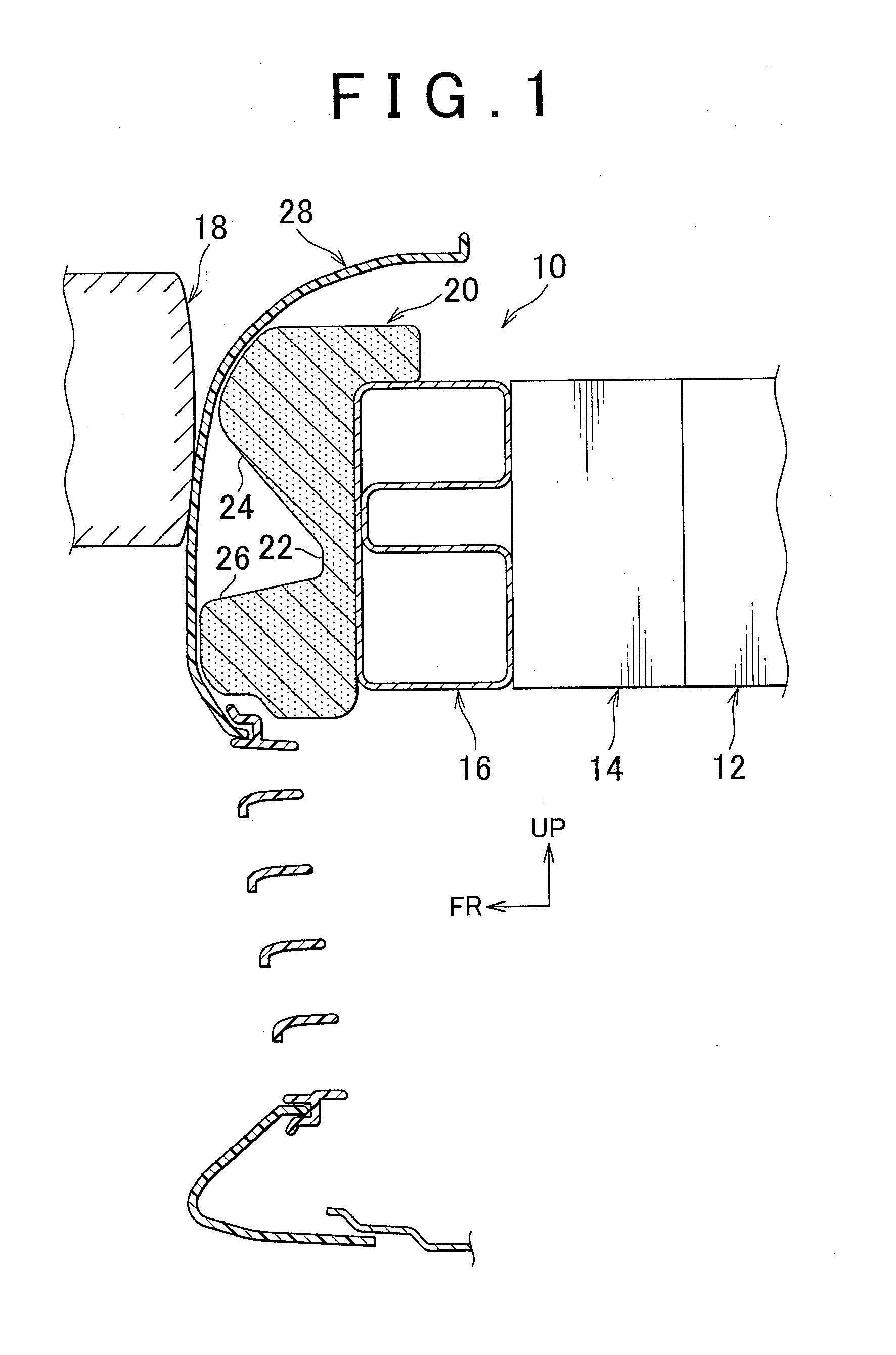
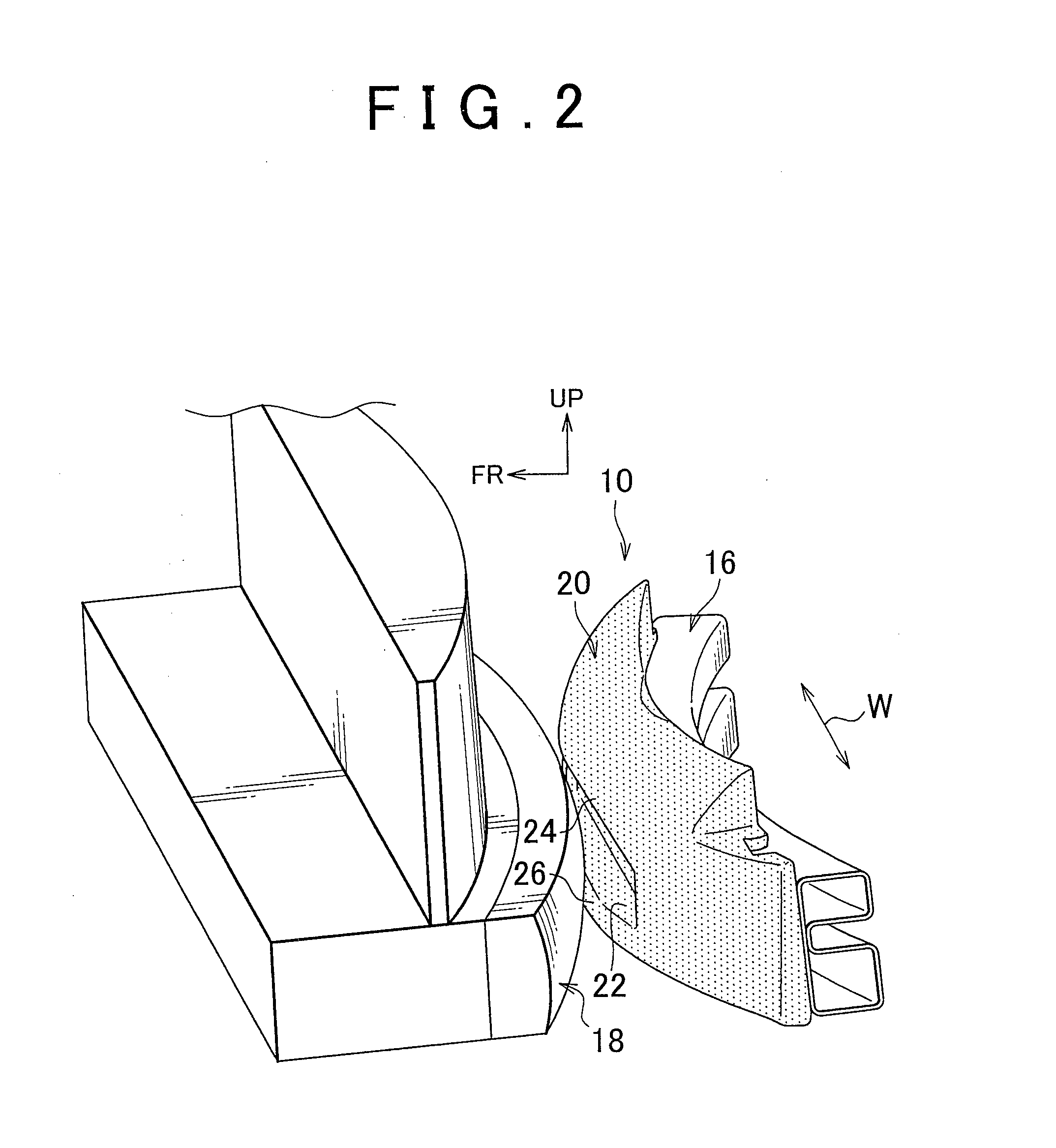
[0049]Hereinafter, a bumper structure according to the first embodiment of the invention will be described with reference to the drawings. The description of the first embodiment will be made on an example, in which the bumper structure of an aspect of the invention is incorporated in the front bumper of a vehicle that is relatively small in height, such as sports cars. Note that, in the drawings, the arrow “FR” indicates the direction toward the front side of the vehicle, the arrow “UP” indicates the direction toward the upper side of the vehicle, and the arrow “W” indicates the lateral direction of the vehicle.

[0050]As shown in FIG. 1, the bumper structure 10 of the first embodiment includes a pair of front side members 12 provided at the respective lateral sides of the vehicle and extending in the longitudinal direction of the vehicle, and a bumper reinforcement 16 extending in the lateral direction of the vehicle is attached on the vehicle front side ends of the respective front...

second embodiment

[0075]Next, a bumper structure according to the second embodiment of the invention will be described with reference to FIG. 5. Note that the elements identical to those in the first embodiment are denoted by the same numerals, and the descriptions on them will be omitted. The second embodiment is an example, in which the bumper structure of an aspect of the invention is incorporated in the rear bumper of a vehicle that is relatively small in height, such as supports cars.

[0076]As shown in FIG. 5, in the bumper structure 10 of the second embodiment, the reference numeral 128 indicates a rear bumper cover and the reference numeral 116 indicates a rear bumper reinforcement, and the bumper absorber 20 is attached on the vehicle rear side face of the bumper reinforcement 116.

[0077]The bumper structure 10 of the second embodiment, which is applied to a rear bumper, is substantially the same as the bumper structure 10 of the first embodiment, which is applied to a front bumper. The shape o...

third embodiment

[0080]Next, a bumper structure according to the third embodiment of the invention will be described with reference to FIG. 6. Note that the elements identical to those in the first embodiment are denoted by the same numerals, and the descriptions on them will be omitted. The third embodiment is an example, in which the bumper structure of an aspect of the invention is incorporated in the front bumper of a vehicle that is relatively large in height, such as RVs.

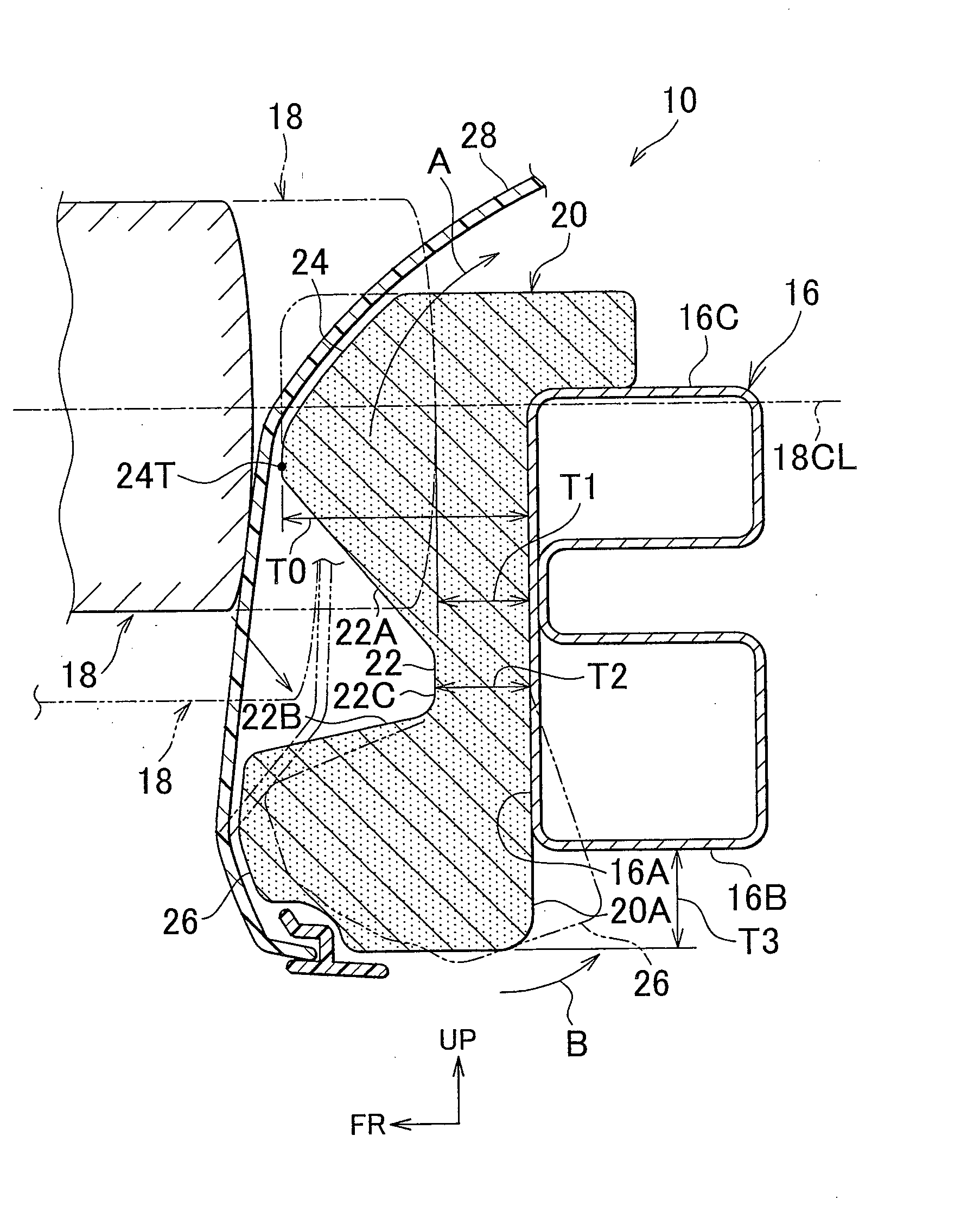
[0081]As shown in FIG. 6, the vertical level of the top face 16C of the bumper reinforcement 16 in the third embodiment, as measured from the road surface, is set higher than that of the top face 16C of the bumper reinforcement 16 in the first embodiment, with respect to the vertical center level 18CL of the barrier 18. The upper portion of the bumper absorber 20 protrudes upward beyond the top face 16C of the bumper reinforcement 16 (refer to the length “T3” in FIG. 6), but it does not protrude toward the rear side of the veh...


PUM


Abstract

A recess is formed at the center of a bumper absorber, provided on the vehicle outer side of a bumper reinforcement, so as to face forward, and an upper recess wall face of an upper absorber portion located on the upper side of the recess is inclined downward. If the subject vehicle is small in height and the amount of vertical overlap between the bumper absorber and the rear bumper of other vehicle (a barrier used in the narrow vertical overlap barrier test of the IIHS) is small, in the initial collision stage, the rear bumper of the other vehicle is guided by the inclined upper recess wall face to move relatively downward while the bumper of the subject vehicle moves relatively upward, preventing underride, increasing the amount of vertical overlap between the rear bumper of the other vehicle and the bumper absorber, and thus achieving reliable impact absorption.

Description

BACKGROUND OF THE INVENTION[0001]1. Field of the Invention[0002]The invention relates to a vehicle bumper structure, and in particular to a bumper structure having a bumper absorber that absorbs an impact upon collision with an object.[0003]2. Description of the Related Art[0004]A bumper absorber (impact absorption member) for absorbing an impact upon collision is provided on the vehicle-longitudinal-direction outer side of each of the bumper reinforcements of the front and rear bumpers of a vehicle. The crash safety tests conducted by the Insurance Institute for Highway Safety (IIHS) in the United States include a narrow vertical overlap barrier test. In this test, an arc-shaped barrier is used, the center portion of which is convexed toward the outer side along the vehicle longitudinal direction. The barrier is vertically offset to partially overlap the bumper of the vehicle, and the front and rear sides of the vehicle are made to collide with the barrier at 10 km / h.[0005]In the c...

Claims


Application Information

Patent Timeline
Patent Type & Authority Applications(United States)
IPC IPC(8): B60R19/18
CPCB60R2019/1873B60R19/18
Inventor CHIBA, KENJISUEHIRO, HITOSHIISHIJIMA, TAKAHIRONAKASHIMA, DAISUKE
Owner TOYOTA JIDOSHA KK
Why Eureka
Try Eureka