Motor control system and the method of controlling motor

Inactive Publication Date: 2013-02-21
LIJU TECH
View PDF9 Cites 9 Cited by
  • Summary
  • Abstract
  • Description
  • Claims
  • Application Information

AI Technical Summary

Benefits of technology

The present invention provides a control system of a motor that can serve both functions of power supply and signal transmission through the same power line. This simplifies the design and reduces the cost of the control system. The control system includes a control apparatus and an actuation apparatus, which work together to control the motor through the power line. The method involves inputting a command and converting it into electrical control signals, transmitting the signals to the power line, receiving both the signals and the power from the power line, and converting the signals into a command to adjust the power supplying to the motor. The actuation apparatus includes a motor actuator and a communication module receiving the signals and converting them into a command to control the motor.

Problems solved by technology

As the technology improving, some devices need a driving power with various speeds that the conventional motors with single speed cannot afford such devices.
In such motor of adjustable speed, it needs a power line to connect the motor, a driver, and the controller, and furthermore, it also needs a signal wire to transmit the control signals that it is complex to wire these three units.
While the motor has the function of monitoring, the wire arrangement is more complex.
In spite of higher cost, the complex wire arrangement may damage the motor by the wrong wire connection.
As a result, the conventional control system of motor still has some drawbacks to be solved.

Method used


Image

  • Motor control system and the method of controlling motor
  • Motor control system and the method of controlling motor
  • Motor control system and the method of controlling motor

Examples


Embodiment Construction

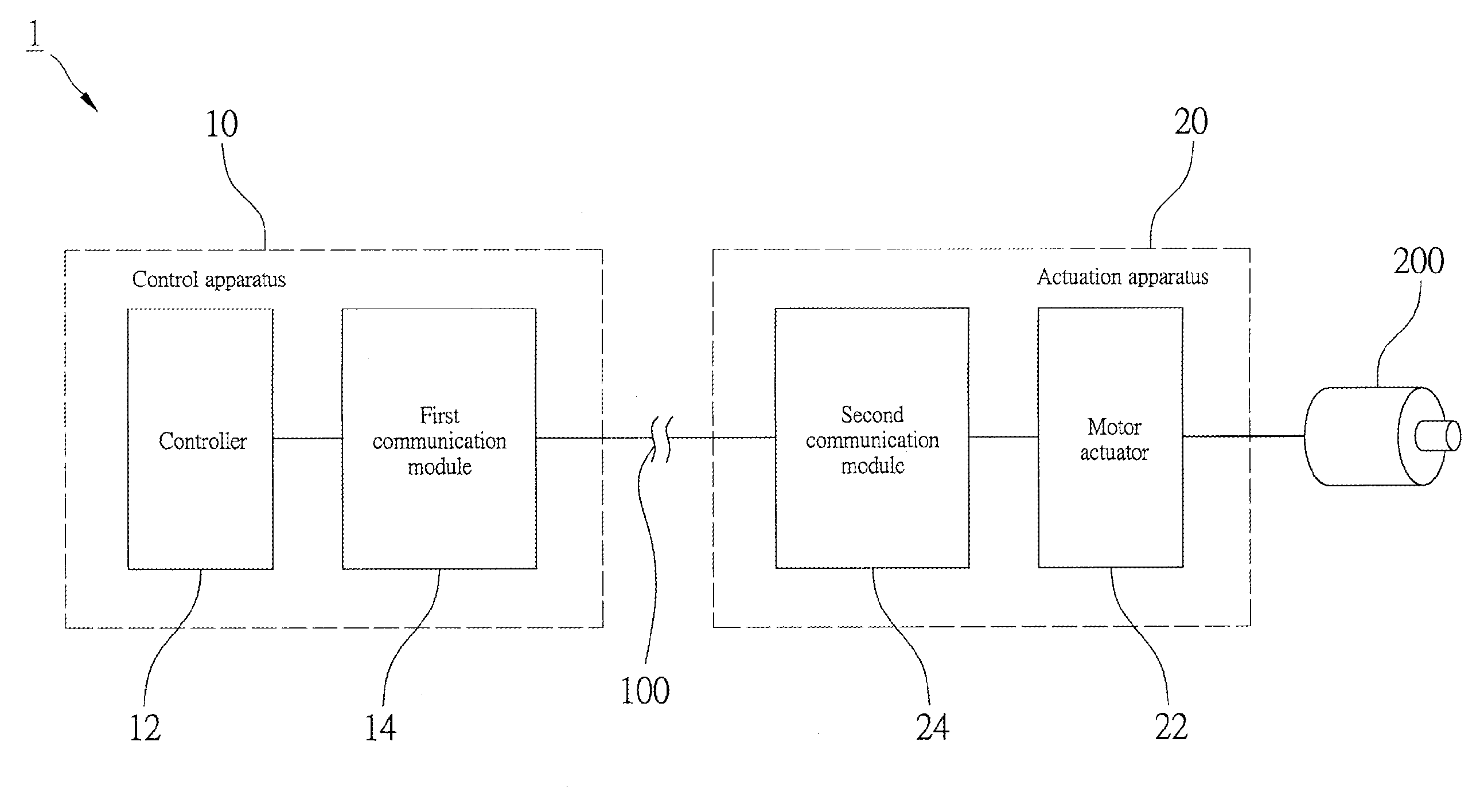
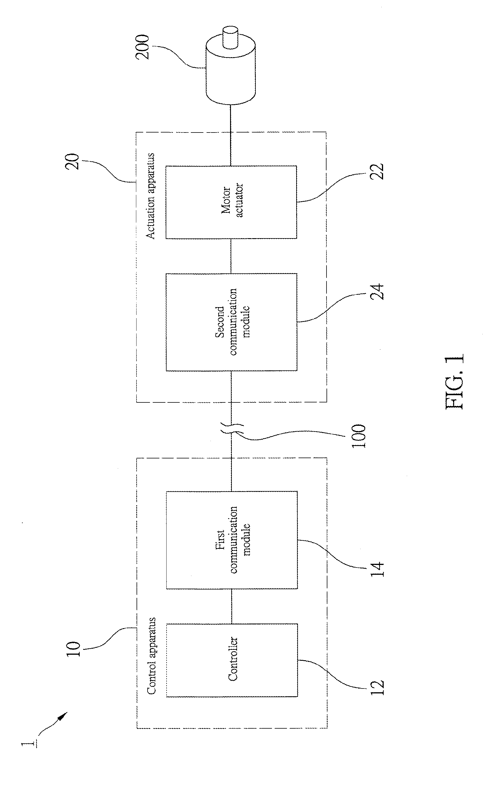
[0018]FIG. 1 shows a control system 1 of a DC brushless motor 200 the first preferred embodiment of the present invention. The control system 1 includes a power line 100 to supply the motor 200 power. In the present invention, the power line 100 supplies AC power.

[0019]The control system 1 includes a control apparatus 10 and an actuation apparatus 20.

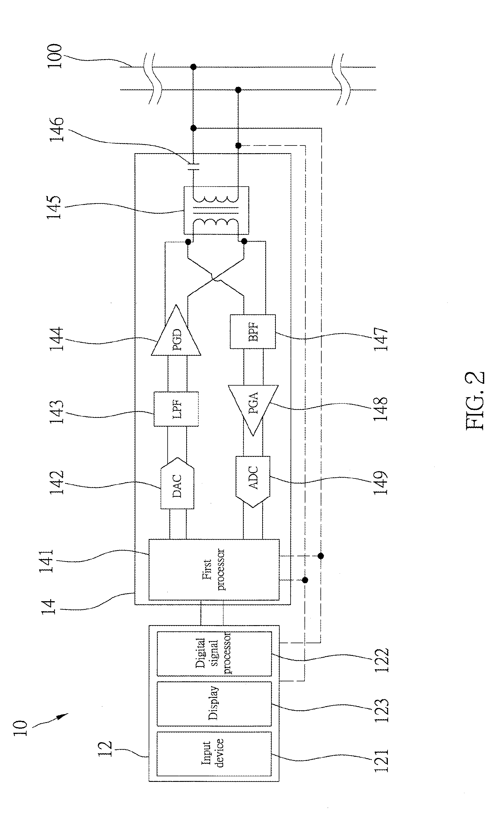
[0020]The control apparatus 10 includes a controller 12 and a first communication module 14. As shown in FIG. 2, the controller 12 has an input device 121, a digital signal processor (DSP) 122, and a display 123. In the present embodiment, the input device 12 is a keyboard for user to input command. It also may includes a mouse, speed controller, or other relative device. The DSP 122 may transform the commands into digital electrical control signals. The display 123 may show what the user inputs. In practice, the controller may be industrial computer, PC, embedded controller, or other relative devices.

[0021]The first communication modul...


PUM


Abstract

The present invention further provides a motor control system, which controls a motor through a power line. The motor control system includes a control apparatus and an actuation apparatus. The control apparatus includes a controller and a first communication module electrically connected to the controller. The controller receives a command and converts the command into electrical control signals. The first communication module receives the electrical control signals from the controller and transmits the electrical control signals to the power line. The actuation apparatus includes a second communication module and a motor actuator electrically connected to the second communication module. The second communication module is connected to the power line to receive the electrical control signals from the control apparatus and convert the electrical control signals into a command. The motor actuator receives the command from the second communication module to change the power supplying to the motor.

Description

BACKGROUND OF THE INVENTION[0001]1. Field of the Invention[0002]The present invention relates generally to a motor, and more particularly to a motor control system and a method of controlling a motor.[0003]2. Description of the Related Art[0004]Motor is a common device in vehicle, machines and some consumer electronic devices. Motors may provide a rotation with a consistent speed to drive an object for rotation or movement. As the technology improving, some devices need a driving power with various speeds that the conventional motors with single speed cannot afford such devices. Therefore, an improved motor equipped with a controller to change voltage, current or frequency to change the speed of the motor is provided to the market for various requirements.[0005]In such motor of adjustable speed, it needs a power line to connect the motor, a driver, and the controller, and furthermore, it also needs a signal wire to transmit the control signals that it is complex to wire these three ...

Claims


Application Information

Patent Timeline
IPC IPC(8): G05B11/01
CPCG05B19/19G05B2219/41321G05B2219/33208G05B2219/33191
Inventor LAI, CHUN-CHENGLIN, HUANG HSIANG
Owner LIJU TECH
Why Eureka
Try Eureka