2n+1 level voltage inverter

a level voltage inverter and level voltage technology, applied in the direction of ac-dc conversion, power conversion systems, electrical equipment, etc., can solve the problems of inability to correct equilibration, voltage and current at the output of the conversion system symmetrie, and excess costs

Active Publication Date: 2013-02-21
GE ENERGY POWER CONVERSION TECH
View PDF3 Cites 36 Cited by
  • Summary
  • Abstract
  • Description
  • Claims
  • Application Information

AI Technical Summary

Benefits of technology

[0021]According to other embodiments, the conversion system includes one or more of the following features, considered alone or according to all technically possible combinations:
[0022]the control means are capable of controlling the switching of the first and second correspon

Problems solved by technology

Such a conversion system is likely to involve electric charge imbalances at the middle points 16, which then causes a dissymmetry of the voltage and current at the output of the conversion system.
However, such equilibration means are effective when the amplitude of the alternating voltage

Method used


Image

  • 2n+1 level voltage inverter
  • 2n+1 level voltage inverter
  • 2n+1 level voltage inverter

Examples


first embodiment

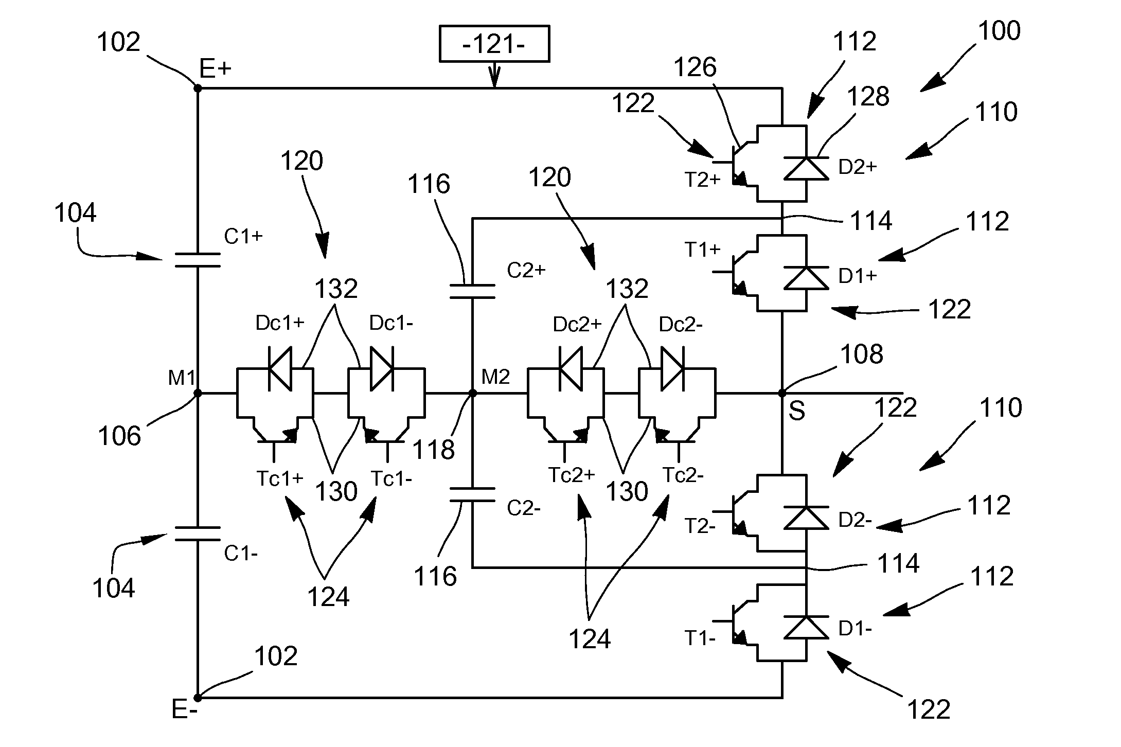
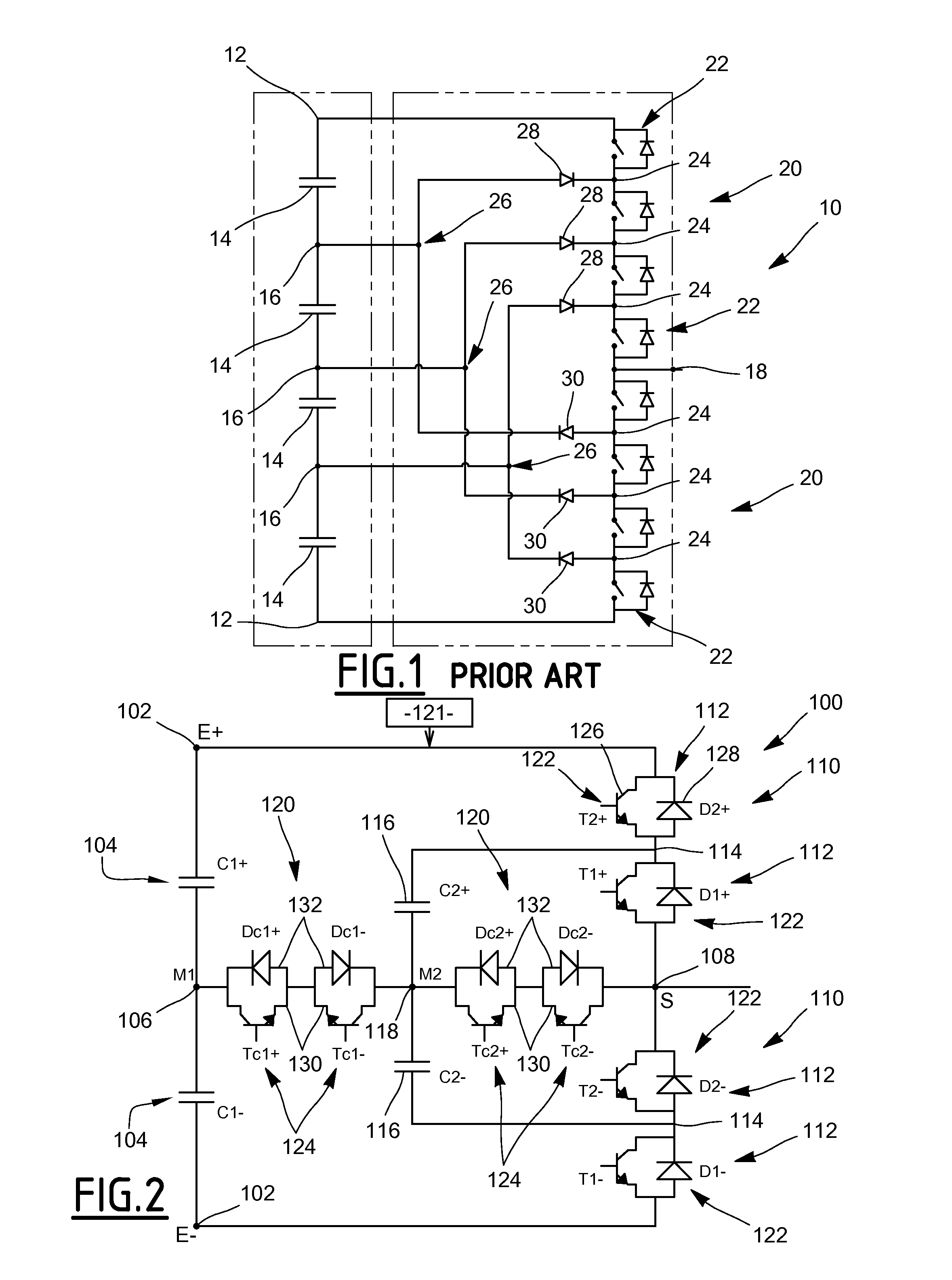
[0038]FIG. 2 shows the voltage conversion system 100 with 2N+1 levels, with N equal to 2, or five levels.

[0039]The conversion system 100 includes two input terminals 102, i.e. a positive terminal denoted E+ and a negative terminal denoted E−, and two voltage generators 104 connected in series between the input terminals 102 and connected to one another by a middle point 106, also denoted M1.

[0040]The conversion system 100 includes, for the or each phase of the output voltage, only one phase being shown in FIG. 2, an output terminal 108, also denoted S, and two switching branches 110 each connected between the output terminal 108 and a respective input terminal 102. Each switching branch 110 comprises two first switching cells 112 connected in series and an intermediate point 114, the first two cells 112 being connected to one another by the intermediate point 114.

[0041]The conversion system 100 also includes, for the or each phase of the output voltage, a pair of capacitors 116, eac...

second embodiment

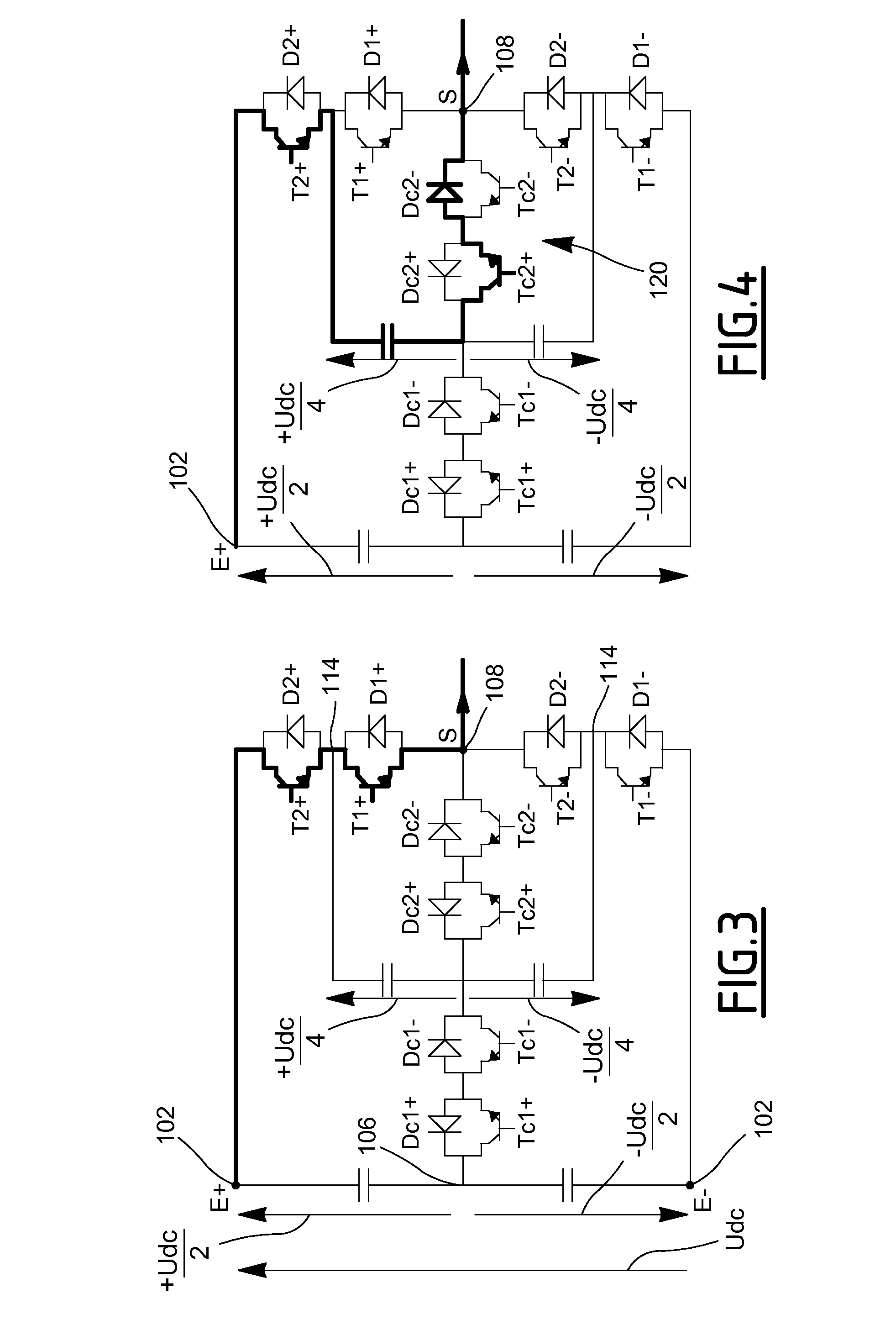
[0123]During the operation of the conversion system 100 the direct voltage between the input terminals 102 is equal to Udc, and the voltage at the terminals of the capacitor C1+ between the middle point 106 and the positive input terminal E+ is then equal to +Udc / 2, the voltage at the terminals of the capacitor C1− between the middle point 106 and the negative input terminal E− being equal to −Udc / 2.

[0124]The voltage at the terminals of the capacitors 116 denoted Ci+, Ci−, respectively, with i between 2 and N, is equal to +(N+1−i)×Udc / 2N, equal to −(N+1−i)×Udc / 2N, respectively. The voltage at the terminals of the capacitors 116 of the last pair of capacitors denoted CN+, CN−, respectively, is then equal to +Udc / 2N, −Udc / 2N, respectively, i being equal to N.

[0125]The operation of this second embodiment has state redundancies with the flowing current, for a same value of the alternating voltage, in one direction, then the other, through each of the capacitors 116 denoted Ci+, Ci−, re...


PUM


Abstract

This system for converting a direct input voltage into an alternating output voltage comprises two input terminals, two voltage generators connected in series between the input terminals and connected to one another by a middle point, as well as, for each phase of the alternating voltage, an output terminal, two switching branches each connected between the output terminal and a respective input terminal, each switching branch comprising N first switching cells connected in series and N−1 intermediate points, the first switching cells successively being connected to one another by a corresponding intermediate point, N being an integer greater than or equal to 2, and control means for controlling the first switching cells. The system includes, for each phase of the alternating voltage, N−1 pair(s) of capacitors, each pair of capacitors being connected between intermediate points of one of the two switching branches and the other of the two switching branches.

Description

CROSS-REFERENCE TO RELATED APPLICATIONS[0001]This application claims benefit of French patent application number 1154283, filed May 17, 2011, which is herein incorporated by reference.FIELD OF THE INVENTION[0002]The present invention relates to a system for converting a direct input voltage into an alternating output voltage comprising at least one phase, the system including:[0003]two input terminals,[0004]two voltage generators connected in series between the input terminals and connected to one another by a middle point,[0005]for the or each phase of the output voltage:[0006]an output terminal,[0007]two switching branches each connected between the output terminal and a respective input terminal, each switching branch comprising N first switching cells connected in series and N−1 intermediate points, the first switching cells successively being connected to one another by a corresponding intermediate point, N being an integer greater than or equal to 2, and[0008]control means for...

Claims


Application Information

Patent Timeline
IPC IPC(8): H02M7/537
CPCH02M7/487H02M1/0095H02M7/4837
Inventor SOUA, SAMIR
Owner GE ENERGY POWER CONVERSION TECH
Why Eureka
Try Eureka