Fast link establishment for wireless stations operating in millimeter-wave band

Inactive Publication Date: 2013-02-21
AVAGO TECH WIRELESS IP SINGAPORE PTE
View PDF5 Cites 50 Cited by
  • Summary
  • Abstract
  • Description
  • Claims
  • Application Information

AI Technical Summary

Problems solved by technology

If other devices are present, collisions may occur that could disrupt the training association being carried out between the responder and the initiator or ...

Method used


Image

  • Fast link establishment for wireless stations operating in millimeter-wave band
  • Fast link establishment for wireless stations operating in millimeter-wave band
  • Fast link establishment for wireless stations operating in millimeter-wave band

Examples


Embodiment Construction

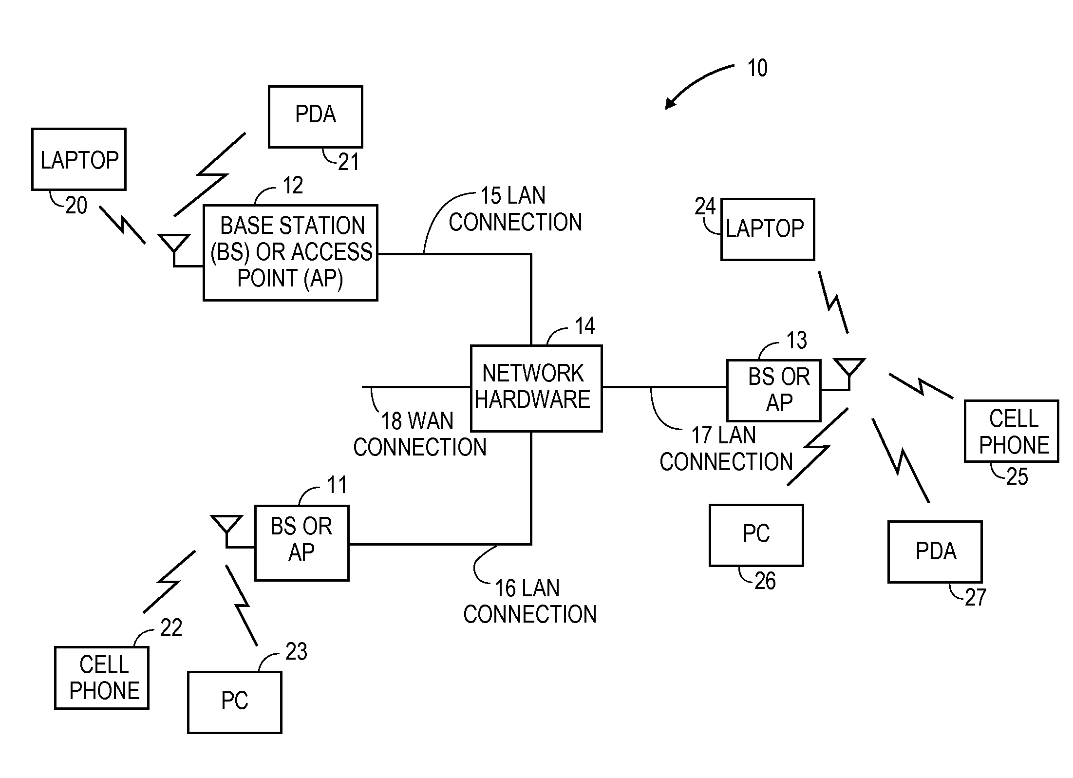
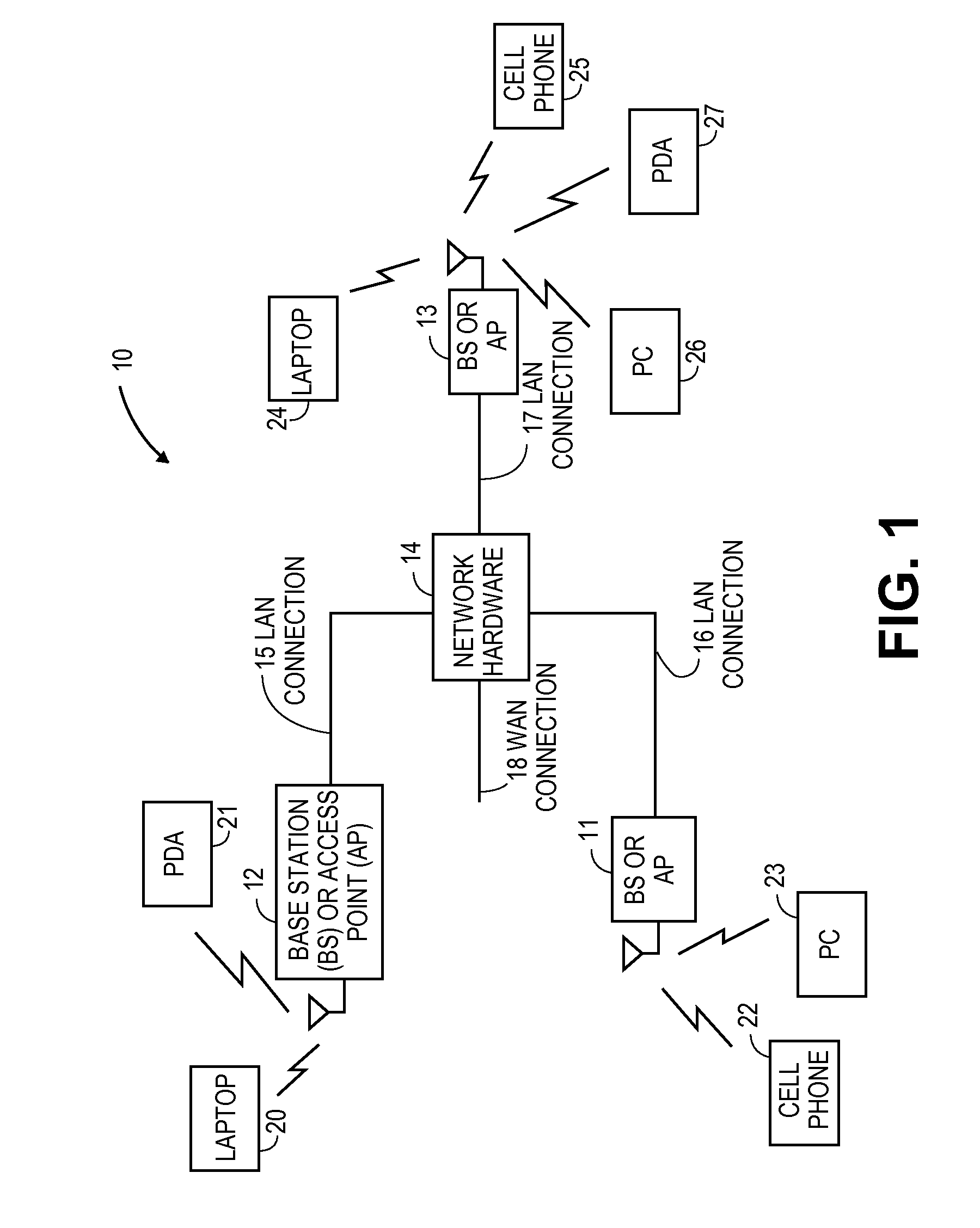
[0020]The embodiments of the present invention may be practiced in a variety of wireless communication devices that operate in a wireless environment or network. The examples described herein pertain to devices that operate approximately within the 60 GHz Band, which is referred to as DBand. Note that at 60 GHz, the frequency wavelength is in millimeters and, hence, identified as millimeter-wave band. However, the invention need not be limited to the 60 GHz Band. Other millimeter wave bands that use directional signal propagation may also implement the invention. Furthermore, the examples described herein reference specific designations, such as Sector Level Sweep (SLS), Sector Sweep (ScS), Association Beamforming Training (A-BFT), Beacon Transmission Interval (BTI), Feedback frame (FF), etc. However, the invention need not be limited to such specific applications or designations. The invention may be readily adapted to other usages where directional beamforming signals are utilized...


PUM


Abstract

A technique to transmit feedback frames from a control point in each slot of an Association-Beamforming Training Period, as specified in a 60 GHz DBand specification, where at least one sector sweep frame is transmitted from a responding station and at least one sector sweep frame is received by the control point, in order to increase the chance of establishing a directional communication link between the control point and the station.

Description

BACKGROUND OF THE INVENTION[0001]1. Technical Field of the Invention[0002]The embodiments of the invention relate to wireless communications and, more particularly, to linking of two devices at millimeter-wave bands.[0003]2. Description of Related Art[0004]Various wireless communication systems are known today to provide communication links between devices, whether directly or through a network. Such communication systems range from national and / or international cellular telephone systems, the Internet, point-to-point in-home systems, as well as other systems. Communication systems typically operate in accordance with one or more communication standards or protocols. For instance, wireless communication systems may operate using protocols, such as IEEE 802.11, Bluetooth™, advanced mobile phone services (AMPS), digital AMPS, global system for mobile communications (GSM), code division multiple access (CDMA), local multi-point distribution systems (LMDS), multi-channel-multi-point dis...

Claims


Application Information

Patent Timeline
IPC IPC(8): H04W76/02
CPCH04W28/06H04B7/0619H04W16/28H04B7/0695
Inventor XU, ZHEMINLU, GANG
Owner AVAGO TECH WIRELESS IP SINGAPORE PTE
Why Eureka
Try Eureka