Surgical Instruments With Removable Components

a surgical instrument and removable technology, applied in the field of surgical instruments with removable components, can solve the problems of contaminated electrodes, less effective transecting of sealed tissue after repeated use, and contaminated tissue-contacting components of electrosurgical forceps, etc., to achieve the effect of facilitating the movement of opposed jaw members and greater flexibility

Inactive Publication Date: 2013-02-21
TYCO HEALTHCARE GRP LP
View PDF4 Cites 139 Cited by
  • Summary
  • Abstract
  • Description
  • Claims
  • Application Information

AI Technical Summary

Benefits of technology

[0013]The opposed jaw members may be operatively coupled to the distal end of the handle assembly by an elongated shaft extending therebetween. The flexible circuit may extend from the at least one jaw member proximally into the elongated shaft, and the flexible circuit may be constructed of a flexible polymer substrate in a substantially flat configuration. The flexible circuit may include a region of relatively greater flexibility to facilitate movement of the opposed jaw members between the open and closed positions.

Problems solved by technology

When the adjacent layers of tissue include the walls of a blood vessel, sealing the tissue may result in hemostasis.
In use, various tissue-contacting components of an electrosurgical forceps tend to become contaminated or degraded.
For example, electrodes may become contaminated as portions of the treated tissue adhere to the tissue-contacting surfaces of the electrodes.
Also, a knife blade may become dull and less effective in transecting sealed tissue after repeated use, even in a single surgical procedure.
Providing a reusable electrosurgical forceps, however, presents various challenges.
For example, the complexity of an electrosurgical forceps tends to result in fairly labor intensive cleaning procedures to prepare the forceps for subsequent use.
Improper cleaning may result in dangerous contamination being introduced surgical site.
Many of these instruments require arduous disassembly and reassembly procedures that require extensive training, and may discourage use of the instrument.

Method used


Image

  • Surgical Instruments With Removable Components
  • Surgical Instruments With Removable Components
  • Surgical Instruments With Removable Components

Examples


Embodiment Construction

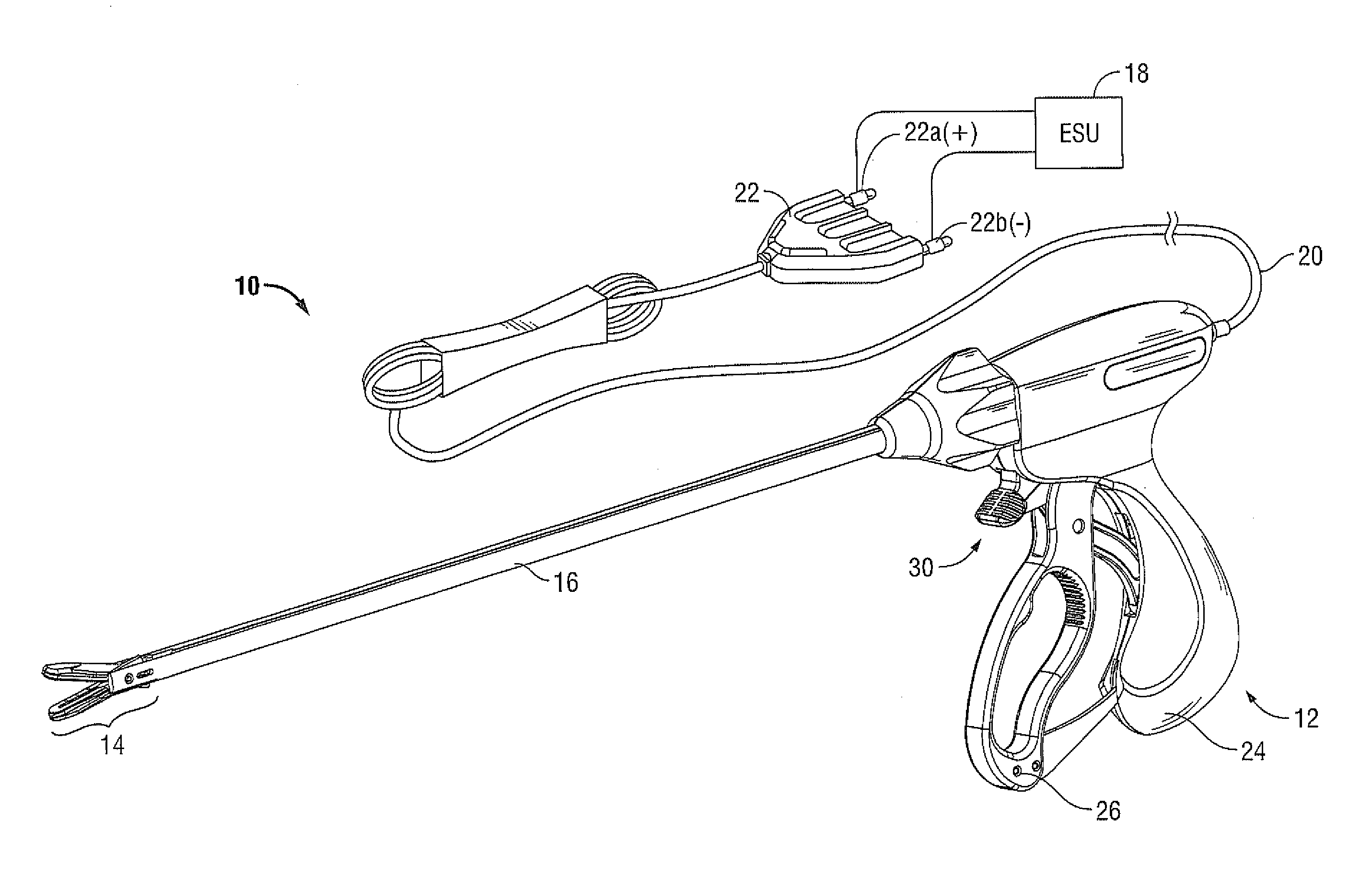
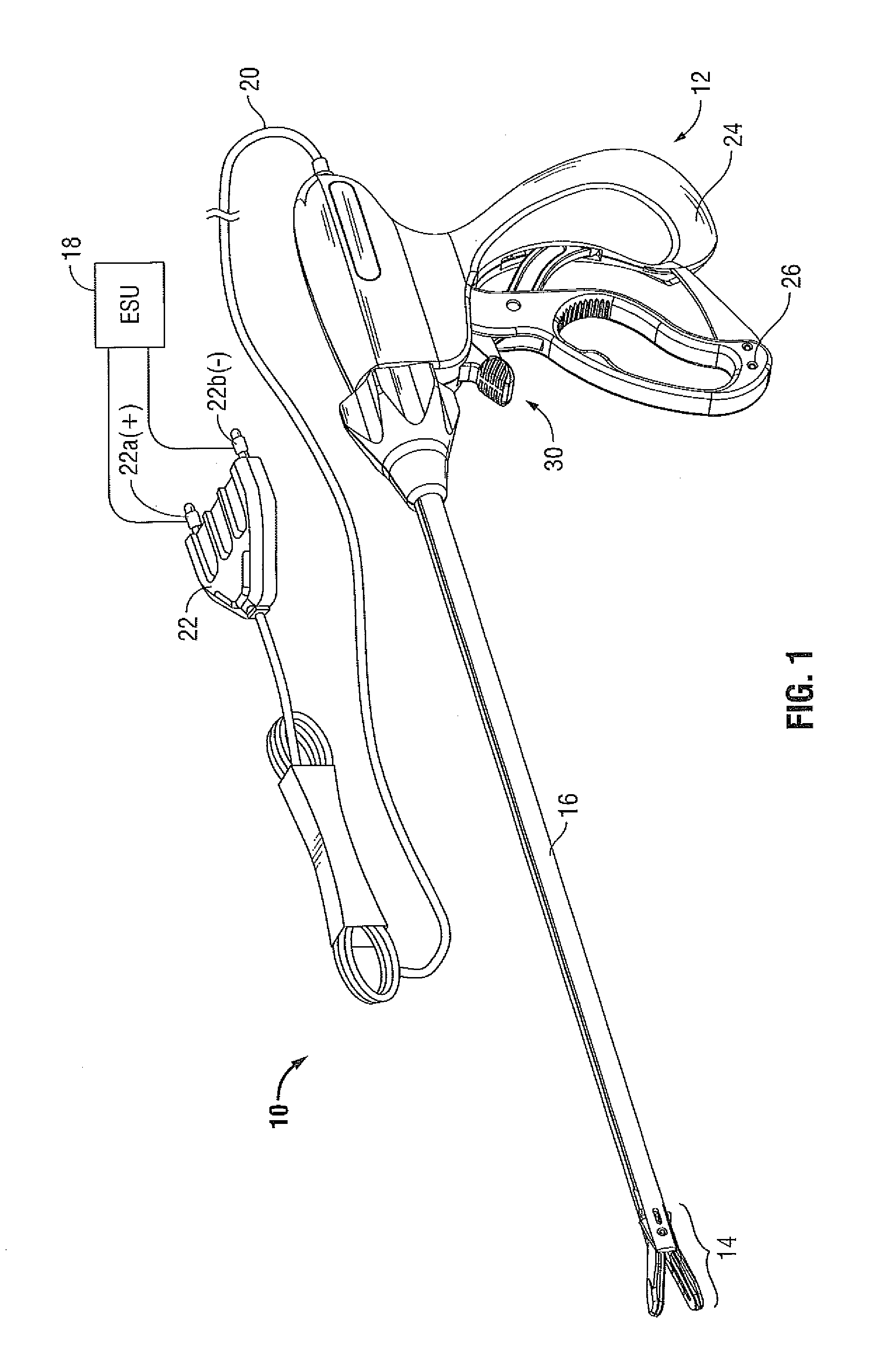
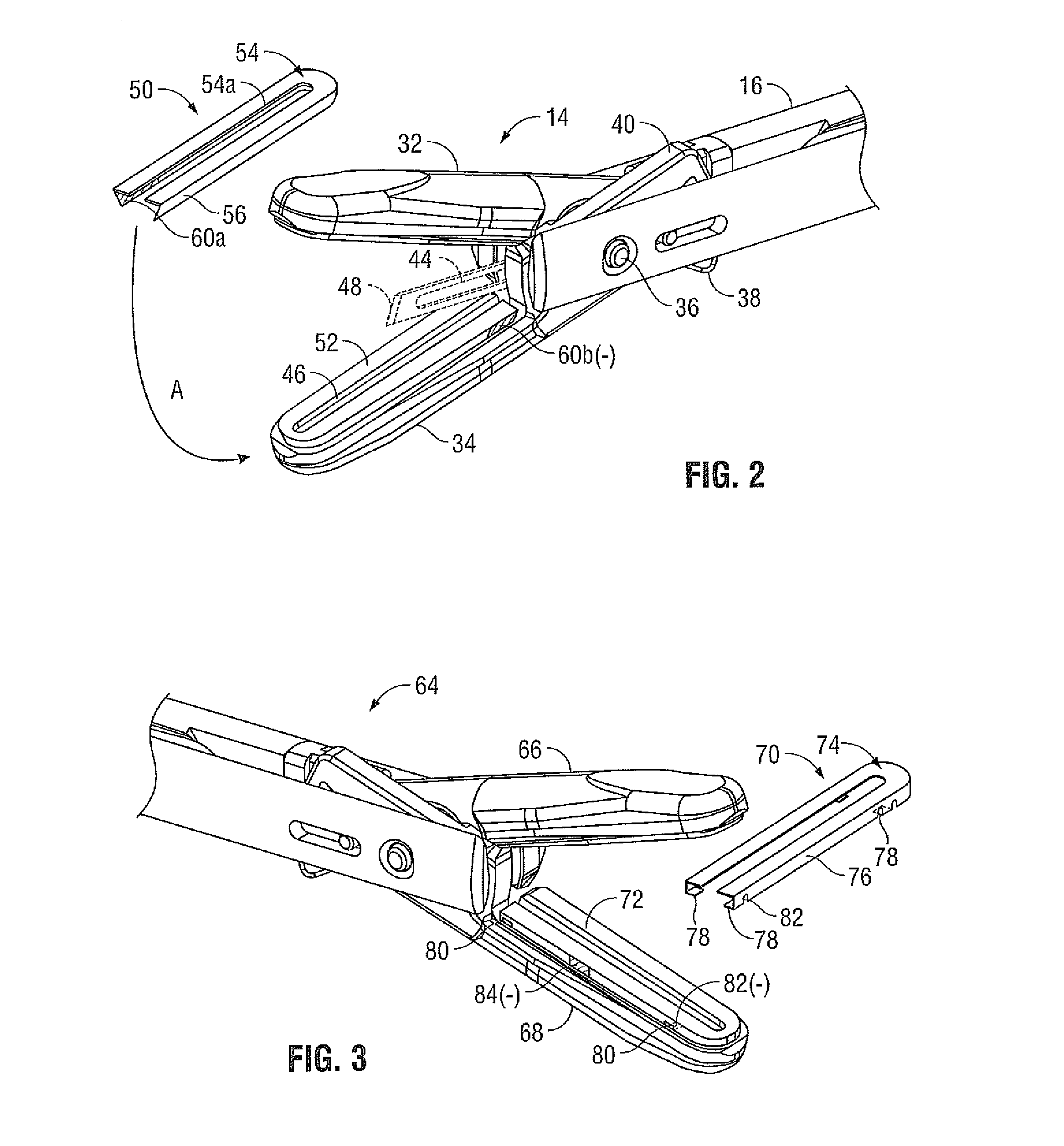
[0030]Referring initially to FIG. 1, an embodiment of an electrosurgical instrument 10 is depicted. The instrument 10 includes a handle assembly 12 for remotely controlling an end effector 14 through an elongated shaft 16. Although this configuration is typically associated with instruments for use in laparoscopic or endoscopic surgical procedures, various aspects of the present disclosure may be practiced with traditional open instruments, and in connection with endoluminal procedures as well.

[0031]The instrument 10 is coupled to a source of electrosurgical energy, e.g., an electrosurgical generator 18. The generator 18 may include devices such as the LIGASURE® Vessel Sealing Generator and the Force Triad® Generator as sold by Covidien. A cable 20 extends between the handle assembly 12 and the generator 18, and includes a connector 22 for coupling the instrument 10 to the external generator 18. In other embodiments (not shown) a battery powered instrument may be provided in which a...


PUM


Abstract

A surgical instrument includes a handle coupled to a source of electrosurgical energy. A pair of opposed jaw members is operatively coupled to a distal end of the handle such that the jaw members selectively move between open and closed positions. A base supported on one of the jaw members includes a mechanical mating feature and an electrically conductive region in electrical communication with the source of electrosurgical energy. A selectively removable seal plate includes a complementarily engaging a mechanical mating feature and an electrically conductive region positioned to contact the electrically conductive region of the base when the mechanical mating features of the base and seal plate are engaged. The complimentarily-engaging mechanical mating features include a pair of spaced protrusions and a pair of spaced recesses open to opposing sides of the base or the seal plate such that the seal plate may be twisted onto the base.

Description

BACKGROUND[0001]1. Technical Field[0002]The present disclosure relates generally to the field of reposable or reusable surgical instruments. In particular, the disclosure relates to instruments having separable and replaceable components to provide clean, sterile or refurbished surfaces in each instance of use.[0003]2. Background of Related Art[0004]Instruments such as electrosurgical forceps are commonly used in open and endoscopic surgical procedures to coagulate, cauterize and seal tissue. Such forceps typically include a pair of jaws that can be controlled by a surgeon to grasp targeted tissue, such as, e.g., a blood vessel. The jaws may be approximated to apply a mechanical clamping force to the tissue, and are associated with at least one electrode surface to permit the delivery of electrosurgical energy to the tissue. The combination of the mechanical clamping force and the electrosurgical energy has been demonstrated to join adjacent layers of tissue captured between the jaw...

Claims


Application Information

Patent Timeline
Patent Type & Authority Applications(United States)
IPC IPC(8): A61B18/18
CPCA61B18/1445A61B2018/1495A61B2018/1455A61B2018/0063A61B2017/00477
Inventor KERR, DUANE E.EVANS, ALLAN J.RESCHKE, ARLAN J.SHARP, ROBERT M.NAU, JR., WILLIAM H.HORNER, GLENN A.HUSEMAN, MARK J.
Owner TYCO HEALTHCARE GRP LP
Why Eureka
Try Eureka