
System for performing predefined fastener installtion procedures

a technology of predefined fastener installation and predefined procedures, which is applied in the direction of wrenches, manufacturing tools, portable power-driven tools, etc., can solve the problems of not being able to achieve the desired flange joint, consuming a large amount of time, and presenting similar problems in other complex assembly procedures. achieve the effect of fast and accura

Active Publication Date: 2013-02-28
INNOVATION PLUS
View PDF7 Cites 40 Cited by
  • Summary
  • Abstract
  • Description
  • Claims
  • Application Information

AI Technical Summary

Benefits of technology

The patent describes a system that can quickly and accurately put together joints that involve multiple fasteners and are subject to elastic interaction between them. This system can handle rocking and joint relaxation.

Problems solved by technology

Although the problems in achieving such a result have been known for some time, numerous attempts at solving such problems have not been entirely successful.
Nevertheless, and even with load indicating fasteners such as the “I-Bolt®” fasteners which are available from Load Control Technologies of King of Prussia, Pa., it has not previously been possible to reliably achieve a satisfactory flange joint having substantially uniform stress on each of the fasteners without employing a significant number of passes in which each of the series of fasteners is sequentially tightened in a predefined pattern, resulting in a significant amount of time to produce the desired flange joint.
While the foregoing discusses problems associated with the joining of flanges, similar problems are presented in other complex assembly procedures.
Moreover, such problems can further be complicated by the use of various different gasket materials for developing gasketed joints.

Method used


Image

  • System for performing predefined fastener installtion procedures
  • System for performing predefined fastener installtion procedures
  • System for performing predefined fastener installtion procedures

Examples


Embodiment Construction

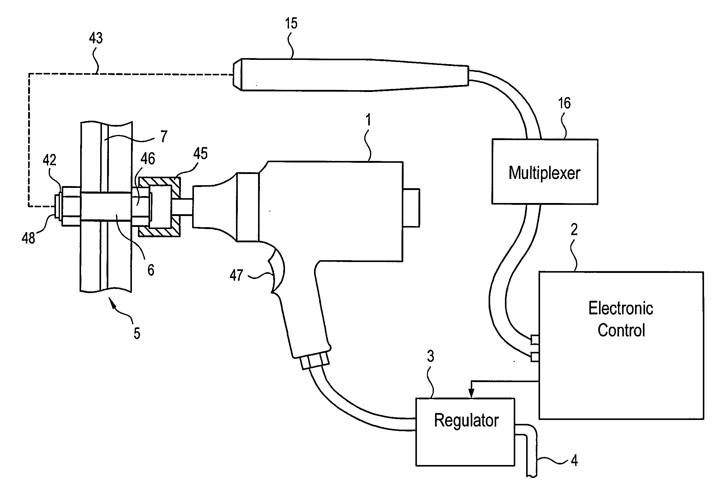
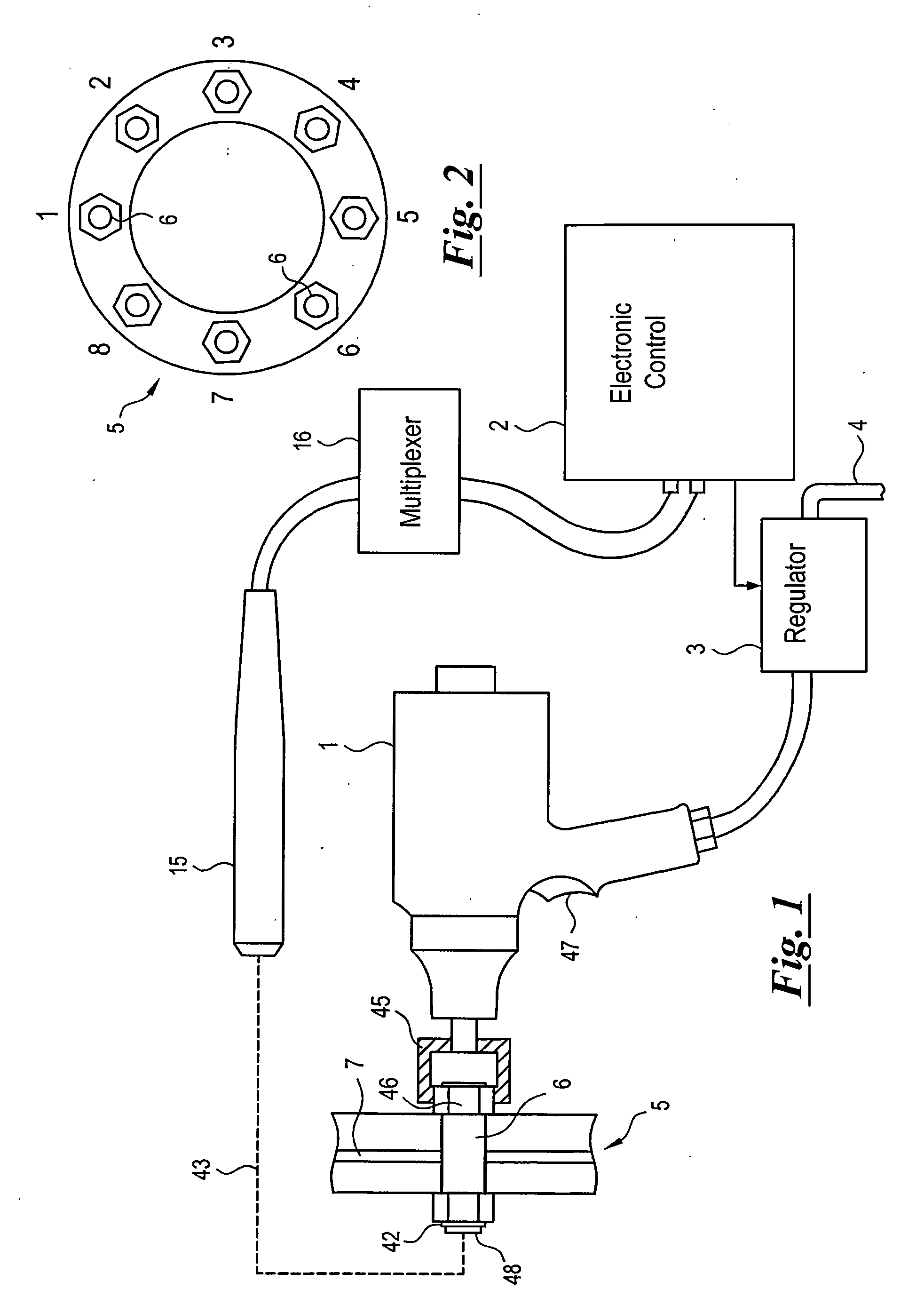
[0025]FIG. 1 shows a preferred embodiment of the present invention which generally includes a pneumatic tool 1, an electronic control 2 for making load measurements in a fastener and for making control decisions based on the load measurements which have been made, and an electronically controlled air pressure regulator 3 associated with the supply line 4 which delivers pressurized air to the pneumatic tool 1 to dynamically control the air pressure supplied to the pneumatic tool 1 during tightening, and to stop the pneumatic tool 1 by reducing the supplied air pressure to zero, using techniques which are disclosed in U.S. Provisional Application No. 60 / 789,828, filed Apr. 6, 2006, and in an International Application filed Apr. 6, 2007, entitled “System for Dynamically Controlling the Torque Output of a Pneumatic Tool”, the subject matter of which is incorporated by reference as if fully set forth herein. While the pneumatic tool 1 shown in FIG. 1 is an impact wrench which is operated...


PUM

PropertyMeasurementUnit
Temperatureaaaaaaaaaa
Responsivityaaaaaaaaaa
Interactionaaaaaaaaaa

Abstract

Complex assembly procedures for joining components with plural fasteners are accomplished using predefined procedures for performing a multi-step assembly of a joint using a dynamically controllable assembly tool, or to inspect an assembled joint. An assembly tool is coupled with an electronically controlled regulator for reducing the tightening rate, or the load increase per impact for an impact or impulse tool, so the tool can be stopped precisely at a specified stopping load or torque. The predefined procedures for performing the desired tightening operation are established in a controller coupled with the electronically controlled regulator, for dynamically controlling the assembly tool. The system can be used to assemble joints involving multiple fasteners and which are subject to elastic interaction between the fasteners, rocking, or joint relaxation, and in assembly or inspection operations in which an operator is to be guided through a particular sequence of instructions.

Description

BACKGROUND OF THE INVENTION[0001]The present invention generally relates to the tightening of bolted joints, and more particularly, to the uniform and accurate tightening of bolted joints formed with multiple fasteners.[0002]The joining of components in any of a variety of industries often requires the development of bolted joints for effectively securing the components to each other. This can include any of a variety of complex assembly procedures for properly securing a series of fasteners associated with an assembled component or combination of components. Examples of such procedures can include applications such as the joining of cylinder head assemblies to cylinder blocks, which is common practice in the automotive industry, the joining of pipe flanges, having applicability to any of a number of industries, and the complex assembly procedures that are prevalent in the aerospace industry, among others.[0003]Irrespective of the application involved, the overall goal is to achieve...

Claims


Application Information

Patent Timeline
IPC IPC(8): B23P19/00
CPCB25B21/002B25B21/02B25B23/0085B25B23/14Y10T29/53B25B23/1453B25F5/00Y10T29/49947B25B23/1425B25B23/1456
Inventor KIBBLEWHITE, IAN E.
Owner INNOVATION PLUS
Learn More