Piston for an internal combustion engine

a technology for pistons and internal combustion engines, which is applied in the direction of pistons, machines/engines, mechanical equipment, etc., can solve the problem of inability to influence the temperature in the central region of the piston crown

Inactive Publication Date: 2013-02-28
MAHLE INT GMBH
View PDF12 Cites 24 Cited by
  • Summary
  • Abstract
  • Description
  • Claims
  • Application Information

AI Technical Summary

Benefits of technology

[0008]It is therefore an object of the present invention to develop a piston in such a manner that influencing the temperature in the central region of the piston crown, during engine operation, is made possible.
[0011]The present invention is suitable for all piston types, i.e. for one-part and multi-part pistons, as well as for pistons having a low construction height. The piston according to the invention has great stability, because no cooling oil channels between the outer cooling channel and the inner cavity, which have a destabilizing effect, as locations of the greatest stress concentration, are provided.
[0016]The amount of the coolant accommodated in the cavity depends on its heat conductivity and the degree of the desired temperature control. Preferably, the volume of the coolant accommodated in the cavity amounts to at most 10% of the volume of the cavity. This has the additional advantage that the coolant is subject to the so-called Shaker effect during engine operation, in that it is moved counter to the stroke direction of the piston in the cavity. During the downward stroke of the piston, the coolant is moved in the direction of the piston crown and can then absorb heat. During the upward stroke of the piston, the coolant is moved in the direction of the piston skirt, and can thus give off the heat it has absorbed, in the direction of the piston skirt. The cooling effect is further improved in this way.
[0017]In a preferred further development, a combustion bowl composed of a heat-resistant steel or a nickel-based alloy can be provided in the piston crown, in order to increase the temperature resistance of the piston according to the invention. The use of a nickel-based alloy has the further advantage that the corrosion resistance of the piston according to the invention is further increased.

Problems solved by technology

In the case of the piston of the stated type, only air is enclosed in the closed cavity, so that influencing the temperature in the central region of the piston crown is not possible.

Method used


Image

  • Piston for an internal combustion engine
  • Piston for an internal combustion engine
  • Piston for an internal combustion engine

Examples


Embodiment Construction

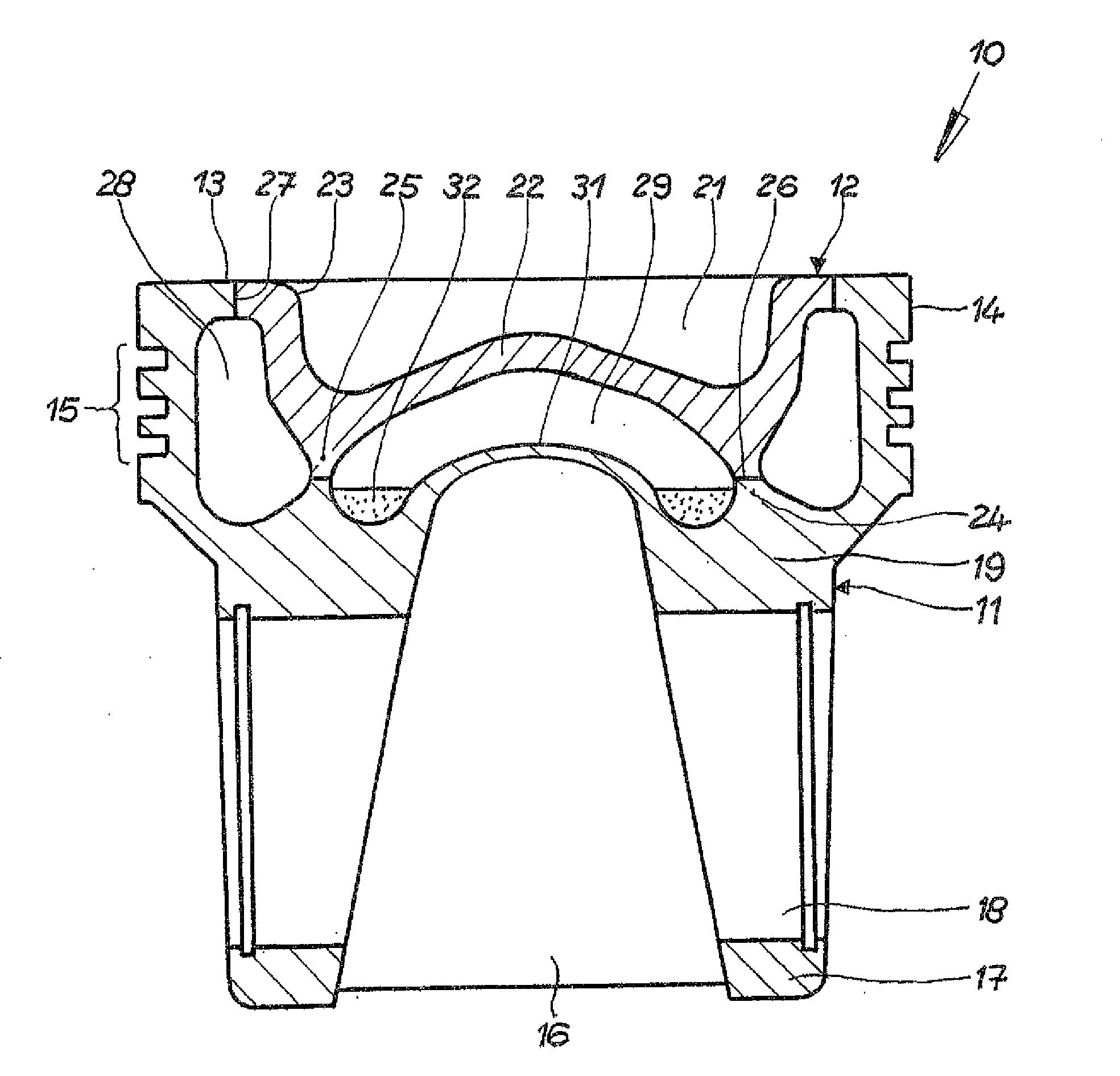
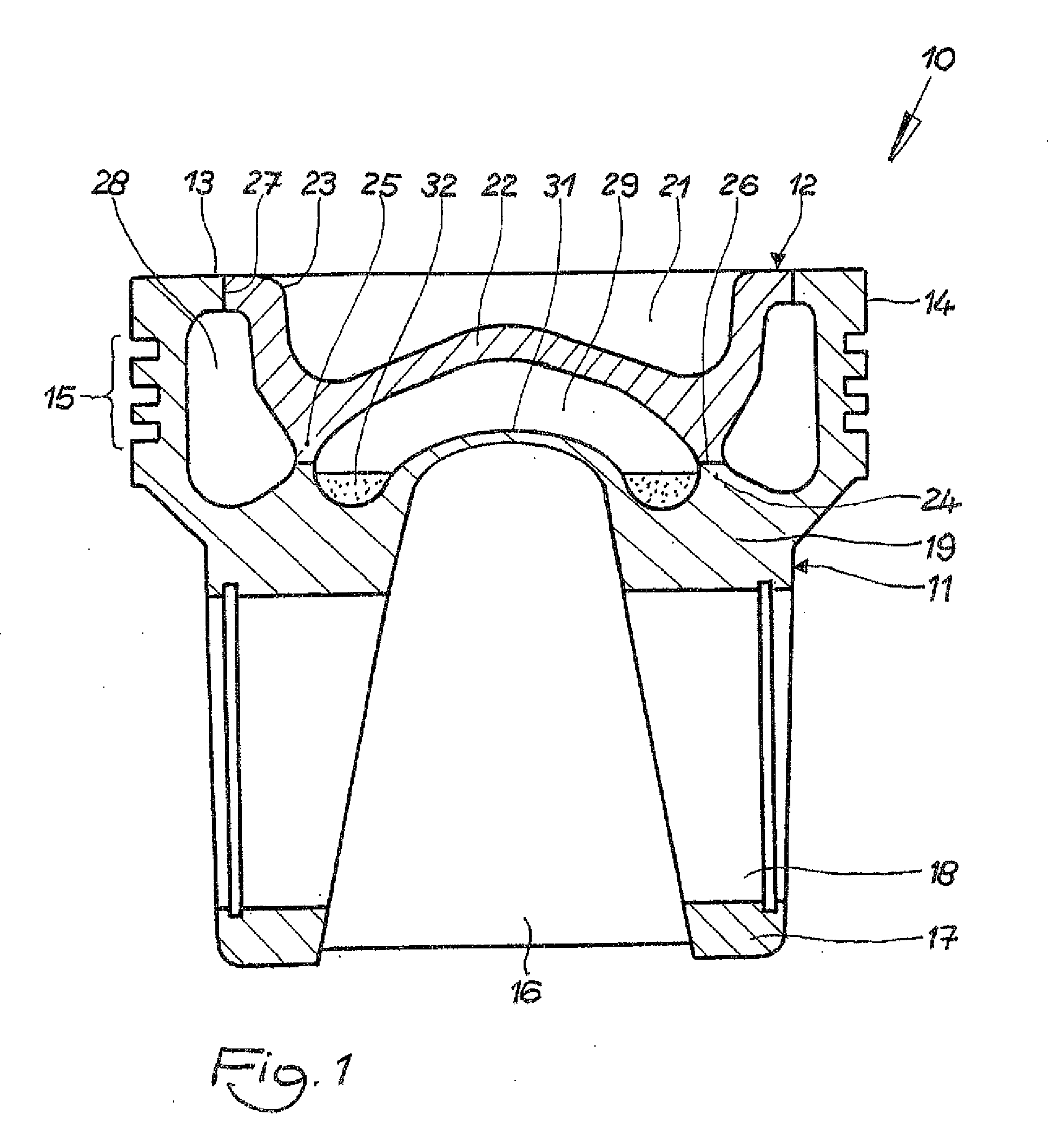
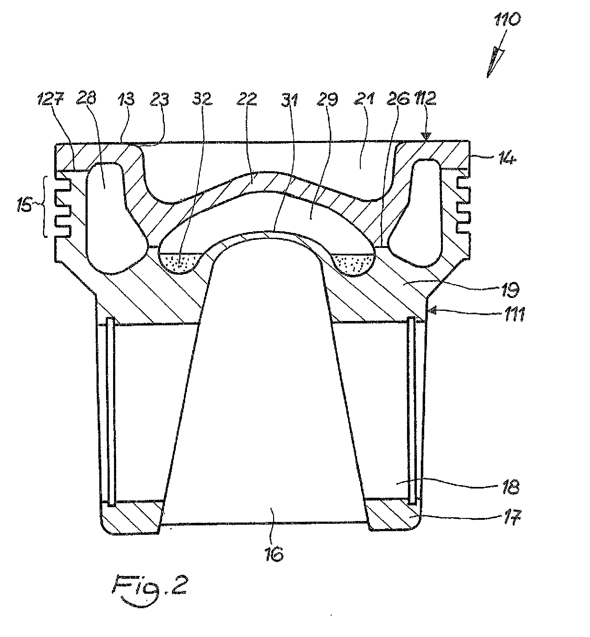
[0025]In the following, the present invention will be described using a two-part piston. Of course, the present invention can also be implemented with other suitable piston types.

[0026]FIG. 1 shows a first exemplary embodiment of a piston 10 according to the invention, in the form of a box piston. Piston 10 according to the invention is composed of a piston base body 11 and a piston crown element 12. Piston base body 11 is forged from a steel material, while piston crown element 12 is produced from a steel material resistant to high heat, or from a nickel-based alloy.

[0027]Piston base body 11 has a part of a piston crown 13, a circumferential top land 14, and a circumferential ring belt 15. Piston base body 11 furthermore has a piston skirt 16 as well as pin bosses 17 having pin bores 18 for accommodating a piston pin (not shown). Pin bosses 17 are connected with underside 13′ of piston crown 13 by way of pin boss supports 19.

[0028]Piston crown element 12 has a part of a piston skir...


PUM


Abstract

A piston for an internal combustion engine has a piston crown, a circumferential ring belt, a circumferential cooling channel in the region of the ring belt, pin boss supports connected below the piston crown, and pin bosses connected with the pin boss supports, as well as a piston skirt. A cavity closed all around is provided below the piston crown and a coolant in the form of a metal or metal alloy having a low melting point is accommodated in the cavity.

Description

CROSS REFERENCE TO RELATED APPLICATIONS[0001]Applicant claims priority under 35 U.S.C. §119 of German Application No. 10 2011 111 319.7 filed Aug. 26, 2011, the disclosure of which is incorporated by reference.BACKGROUND OF THE INVENTION[0002]1. Field of the Invention[0003]The present invention relates to a piston for an internal combustion engine, which has a piston crown, a circumferential ring belt, a circumferential cooling channel in the region of the ring belt, pin boss supports connected below the piston crown, and pin bosses connected with them, as well as a piston skirt. A cavity closed all around is provided below the piston crown.[0004]2. The Prior Art[0005]A piston of this type is described in German Patent Application No. DE 10 2010 009 891.4. In this piston, the circumferential cooling channel serves to control the temperature in the outer region of the piston crown, for example along the edge of a combustion bowl, during engine operation. There, the temperature should...

Claims


Application Information

Patent Timeline
Patent Type & Authority Applications(United States)
IPC IPC(8): F02F3/00
CPCF02F3/22F02F3/18
Inventor HEUSCHMANN, URS
Owner MAHLE INT GMBH
Why Eureka
Try Eureka