Downhole tool and method of use

Active Publication Date: 2013-02-28
THE WELLBOSS CO LLC
View PDF12 Cites 24 Cited by
  • Summary
  • Abstract
  • Description
  • Claims
  • Application Information

AI Technical Summary

Benefits of technology

[0028]The first portion may be configured to expand in a radial direction away from the axis. The composite member and the seal element may be configured to form a reinforced barrier therebetween. The anti-rotation assembly may be configured and usable for the prevention of undesired or inadvertent movement or unwinding of downhole tool components. In aspects, the lock ring may include a guide hole. An end of the anti-rotation device may slidingly engages with or within the guide hole. The protrusion may be configured to permit the tool or tool components to rotate in a first direction, but prevents tool or tool component rotation in a second direction.
[0029]Other emb

Problems solved by technology

Many commercially viable hydrocarbon sources are found in “tight” reservoirs, which means the target hydrocarbon product may not be easily extracted.
The surrounding formation (e.g., shale) to these reservoirs is typically has low permeability, and it is uneconomical to produce the hydrocarbons (i.e., gas, oil, etc.) in commercial quantities from this formation without the use of drilling accompanied with fracing operations.
In these conditions, conventional tools, including those with compressible seal elements, may become ineffective from degradation.
For example, the sealing element may melt, solidify, or otherwise lose elasticity, resulting in a loss the ability to form a seal barrier.
A common problem with retrievable plugs is the accumulation of debris on the top of the plug, which may make it difficult or impossible to engage and remove the plug.
Such debris accumulation may also adversely affect the relative movement of various parts within the plug.
Furthermore, with current retrieving tools, jarring motions or friction against the well casing may cause accidental unlatching of the retrieving tool (resulting in the tools slipping further into the wellbore), or re-locking of the plug (due to activation of the plug anchor elements).
Problems such as these often make it necessa

Method used


Image

  • Downhole tool and method of use
  • Downhole tool and method of use
  • Downhole tool and method of use

Examples


Embodiment Construction

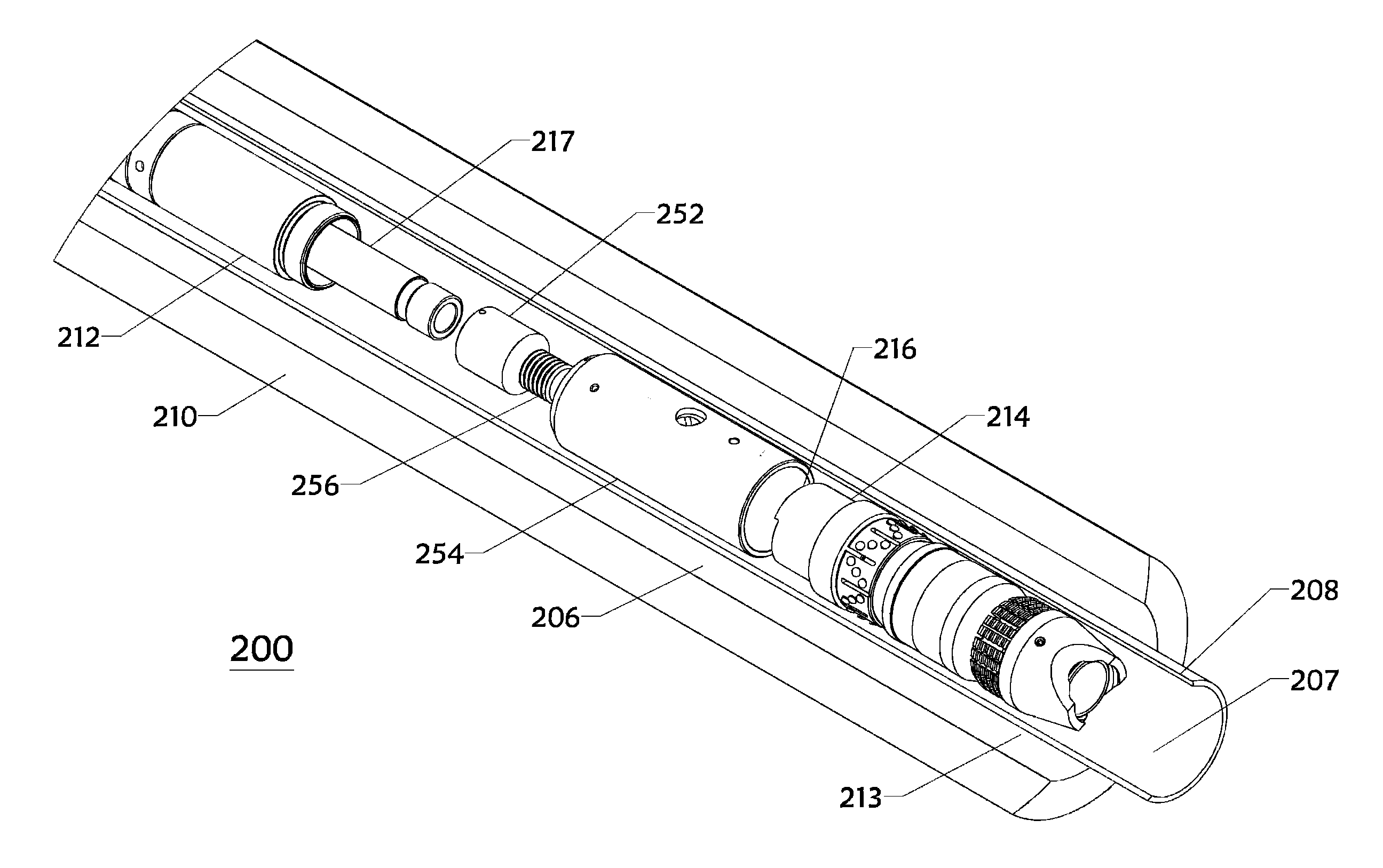
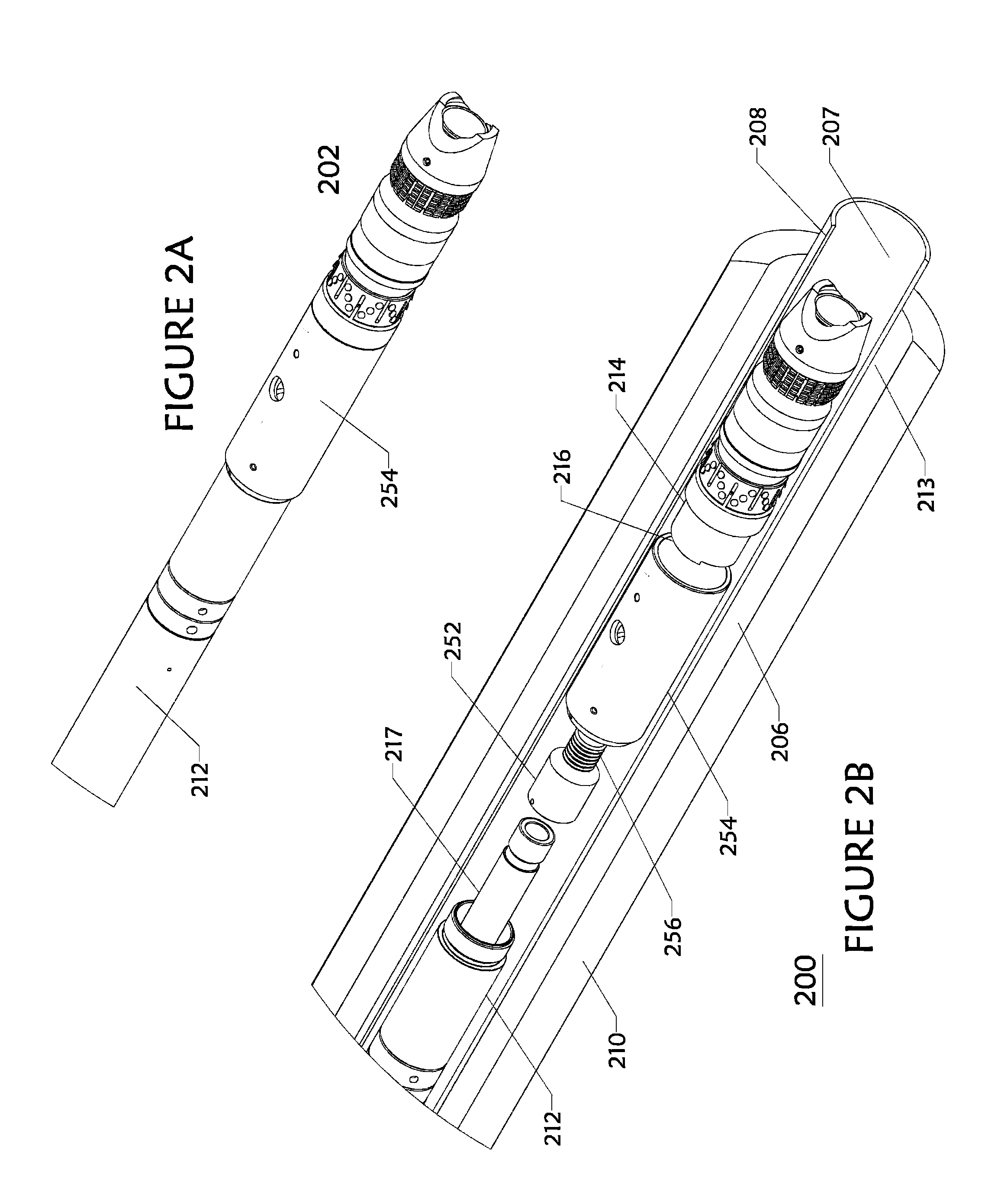
[0063]Herein disclosed are novel apparatuses, systems, and methods that pertain to downhole tools usable for wellbore operations, details of which are described herein.

[0064]Downhole tools according to embodiments disclosed herein may include one or more anchor slips, one or more compression cones engageable with the slips, and a compressible seal element disposed therebetween, all of which may be configured or disposed around a mandrel. The mandrel may include a flow bore open to an end of the tool and extending to an opposite end of the tool. In embodiments, the downhole tool may be a frac plug or a bridge plug. Thus, the downhole tool may be suitable for frac operations. In an exemplary embodiment, the downhole tool may be a composite frac plug made of drillable material, the plug being suitable for use in vertical or horizontal wellbores.

[0065]A downhole tool useable for isolating sections of a wellbore may include the mandrel having a first set of threads and a second set of th...


PUM


Abstract

Embodiments of the disclosure pertain to an anti-rotation assembly for a downhole tool, the anti-rotation assembly having an anti-rotation device; and a lock ring engaged with the anti-rotation device, wherein the anti-rotation device is selected from a group consisting of a spring, a mechanically spring-energized member, and composite tubular piece. Other embodiments pertain to a method of operating a downhole tool that includes an anti-rotation assembly.

Description

CROSS-REFERENCE TO RELATED APPLICATIONS[0001]This application claims the benefit under 35 U.S.C. §119(e) of U.S. Provisional Patent Application Ser. No. 61 / 526,217, filed on Aug. 22, 2011, and U.S. Provisional Patent Application Ser. No. 61 / 558,207, filed on Nov. 10, 2011, each of which are incorporated herein by reference in their entireties for all purposes.STATEMENT REGARDING FEDERALLY SPONSORED RESEARCH OR DEVELOPMENT[0002]Not applicable.BACKGROUND[0003]1. Field of the Disclosure[0004]This disclosure generally relates to tools used in oil and gas wellbores. More specifically, the disclosure relates to downhole tools that may be run into a wellbore and useable for wellbore isolation, and systems and methods pertaining to the same. In particular embodiments, the tool may be a composite plug made of drillable materials.[0005]2. Background of the Disclosure[0006]An oil or gas well includes a wellbore extending into a subterranean formation at some depth below a surface (e.g., Earth'...

Claims


Application Information

Patent Timeline
IPC IPC(8): B28B7/36
CPCE21B23/06E21B33/129E21B17/02E21B19/10E21B19/18E21B33/1208E21B33/128E21B33/134E21B34/08E21B2200/04E21B23/01E21B34/06E21B33/124E21B33/1291E21B33/1292E21B33/1293E21B34/16
Inventor VANLUE, DUKE
Owner THE WELLBOSS CO LLC
Why Eureka
Try Eureka