
Source device and method for controlling magnetic field using two source resonators in wireless power transmission system

a wireless power transmission system and source device technology, applied in the direction of process and machine control, magnetic variable regulation, instruments, etc., can solve the problem of relatively low transmission rate between the source resonator and the target resonator

Active Publication Date: 2013-02-28
SAMSUNG ELECTRONICS CO LTD
View PDF4 Cites 36 Cited by
  • Summary
  • Abstract
  • Description
  • Claims
  • Application Information

AI Technical Summary

Benefits of technology

The patent describes a device and method for controlling a magnetic field to transmit power to another device. The device includes resonators that form the magnetic field and a magnetic field shape determining unit that determines the shape of the magnetic field based on the number and positions of the devices. A phase changing unit can change the phase of the resonators to form the magnetic field in the determined shape. The device can also verify the number and positions of the devices to optimize transmission rates. The technical effects of the patent include improved control over the magnetic field shape and position, which can enhance the efficiency of power transmission between devices.

Problems solved by technology

However, since the source device may not control the magnetic coupling of the source device based on a position of the target device, a transmission rate between the source resonator and the target resonator may be relatively low depending on the position of the target device.

Method used


Image

  • Source device and method for controlling magnetic field using two source resonators in wireless power transmission system
  • Source device and method for controlling magnetic field using two source resonators in wireless power transmission system
  • Source device and method for controlling magnetic field using two source resonators in wireless power transmission system

Examples


Embodiment Construction

[0044]The following detailed description is provided to assist the reader in gaining a comprehensive understanding of the methods, apparatuses, and / or systems described herein. Accordingly, various changes, modifications, and equivalents of the methods, apparatuses, and / or systems described herein will be suggested to those of ordinary skill in the art. The progression of processing steps and / or operations described is an example; however, the sequence of and / or operations is not limited to that set forth herein and may be changed as is known in the art, with the exception of steps and / or operations necessarily occurring in a certain order. Also, description of well-known functions and constructions may be omitted for increased clarity and conciseness.

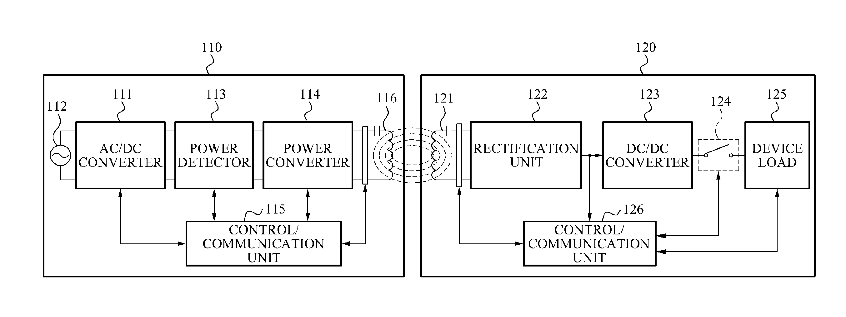
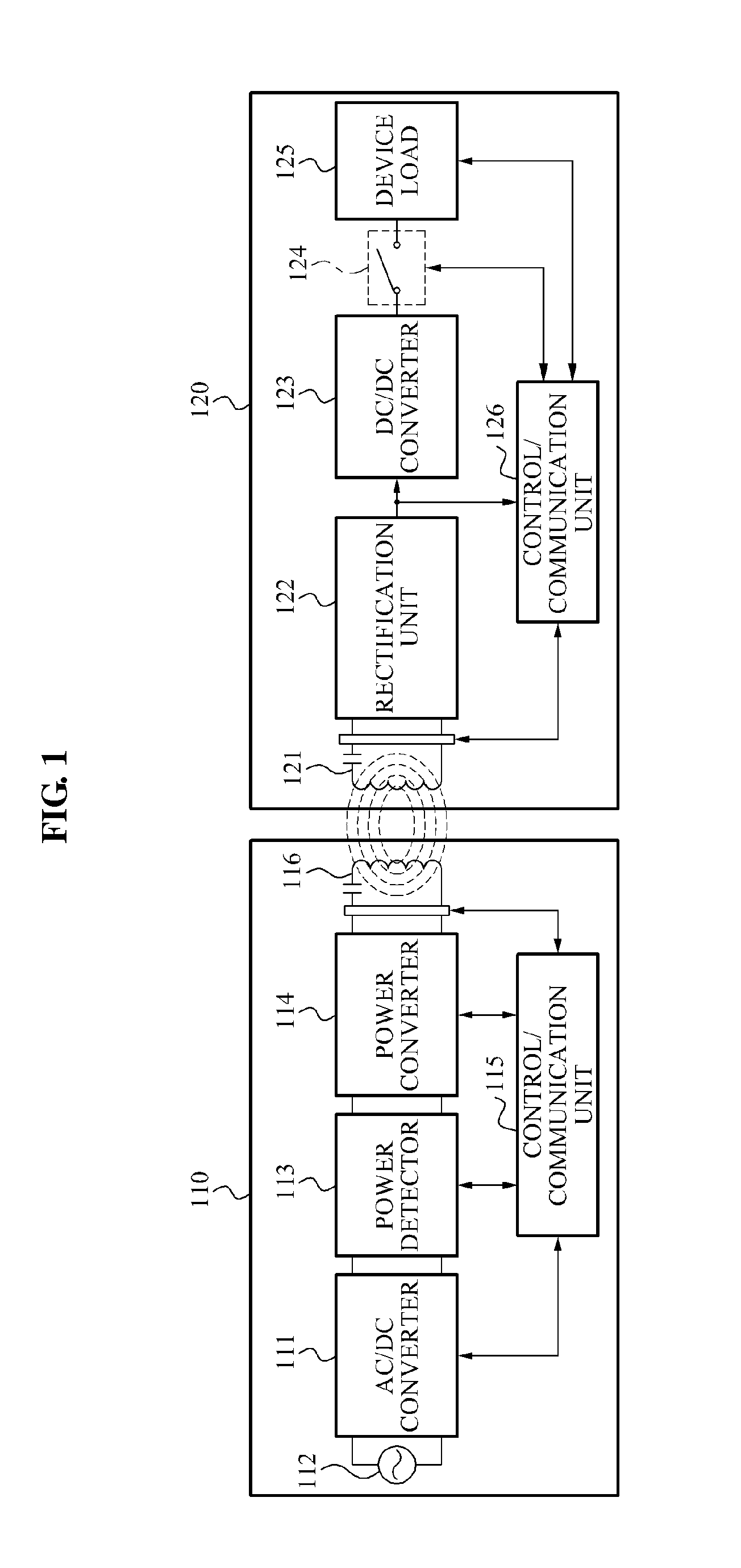
[0045]FIG. 1 is a diagram illustrating an example of a wireless power transmission system. Referring to FIG. 1, the wireless power transmission and charging system includes a source device 110 and a target device 120. The source device...


PUM


Abstract

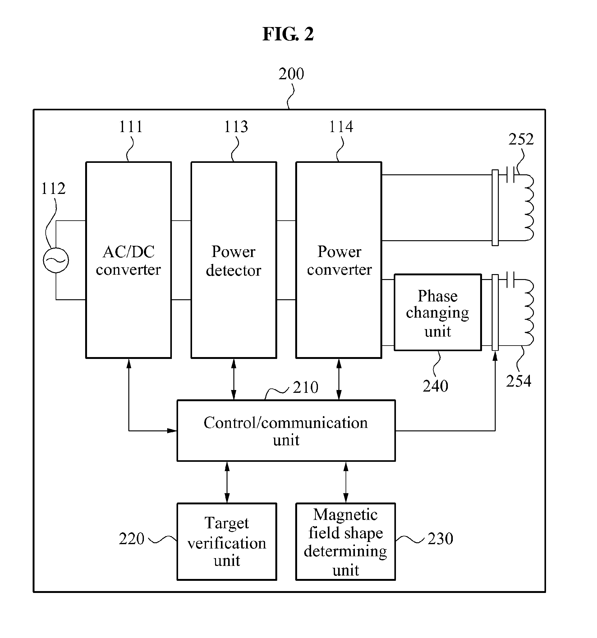
A source device and a method for controlling a magnetic field using two source resonators in a wireless power transmission system are provided. A device configured to control a magnetic field, includes resonators configured to form the magnetic field to transmit power to another device. The device further includes a magnetic field shape determining unit configured to determine a shape of the magnetic field. The device further includes a phase changing unit configured to change a phase of at least one of the resonators to form the magnetic field in the determined shape.

Description

CROSS-REFERENCE TO RELATED APPLICATION(S)[0001]This application claims the benefit under 35 U.S.C. §119(a) of Korean Patent Application No. 10-2011-0085000, filed on Aug. 25, 2011, in the Korean Intellectual Property Office, the entire disclosure of which is incorporated herein by reference for all purposes.BACKGROUND[0002]1. Field[0003]The following description relates to a source device and a method for controlling a shape of a magnetic field in a wireless power transmission system.[0004]2. Description of Related Art[0005]A wireless power refers to energy that is transferred from a wireless power transmitter to a wireless power receiver through magnetic coupling. Accordingly, a wireless power transmission system includes a source device to wirelessly transmit a power, and a target device to wirelessly receive a power. The source device may be referred to as a wireless power transmitter, and the target device may be referred to as a wireless power receiver.[0006]The source device i...

Claims


Application Information

Patent Timeline
Patent Type & Authority Applications(United States)
IPC IPC(8): H02J17/00B60L1/00
CPCB60L11/182Y02T90/121B60L2210/10B60L2210/30B60L2210/40B60L2230/16Y02T10/7088Y02T10/7005Y02T10/7241Y02T90/125Y02T10/7216Y02T90/163Y02T90/14Y02T90/128Y02T90/127Y02T90/122H02J5/005H02J7/025Y02T90/16B60L11/1833B60L53/36B60L53/305B60L53/126H02J2310/48H02J7/00034Y02T10/72Y02T10/7072Y02T10/70Y02T90/12H02J50/90H02J50/80H02J50/12H02J50/40H02J50/70G05F7/00
Inventor KIM, KI YOUNGPARK, EUN SEOKCHOI, JIN SUNGKWON, SANG WOOKKIM, NAM YUNKIM, DONG ZOPARK, YUN KWONRYU, YOUNG HOYOON, CHANG WOOKHONG, YOUNG TACK
Owner SAMSUNG ELECTRONICS CO LTD
Learn More