
LED lamp

a technology of led lamps and lampshades, applied in semiconductor devices of light sources, light and heating apparatuses, gas-filled discharge tubes, etc., can solve the problems of affecting product yield rate, and difficulty in providing the case with operating members, so as to reduce the error of operation and improve the product yield rate

Inactive Publication Date: 2013-02-28
IRIS OHYAMA
View PDF3 Cites 23 Cited by
  • Summary
  • Abstract
  • Description
  • Claims
  • Application Information

AI Technical Summary

Benefits of technology

The present invention aims to provide an LED lamp with reduced erroneous operation. It does this by blocking light from reaching the light receiving element by using a light shielding member, preventing the LED lamp from being turned on when not needed. Additionally, the invention provides an illuminator with a touchless sensor and controller that can adjust its operation even after assembly, improving yield rate in the production process.

Problems solved by technology

Such a thin case, however, may be disadvantageous in that it is difficult to provide the case with operational members such as a power switch, a dimmer knob, etc.
Kitchen illuminators often need to be turned on or off with a wet hand, which poses safety risk as well as hygiene risk.
However, with the optical touchless sensors, it is difficult to manufacture products with desired performance at a high yield rate, due to the variation in performance of the light emitting device and the light receiving element, or the variation in mounting accuracy of the components.

Method used


Image

  • LED lamp
  • LED lamp
  • LED lamp

Examples


first embodiment

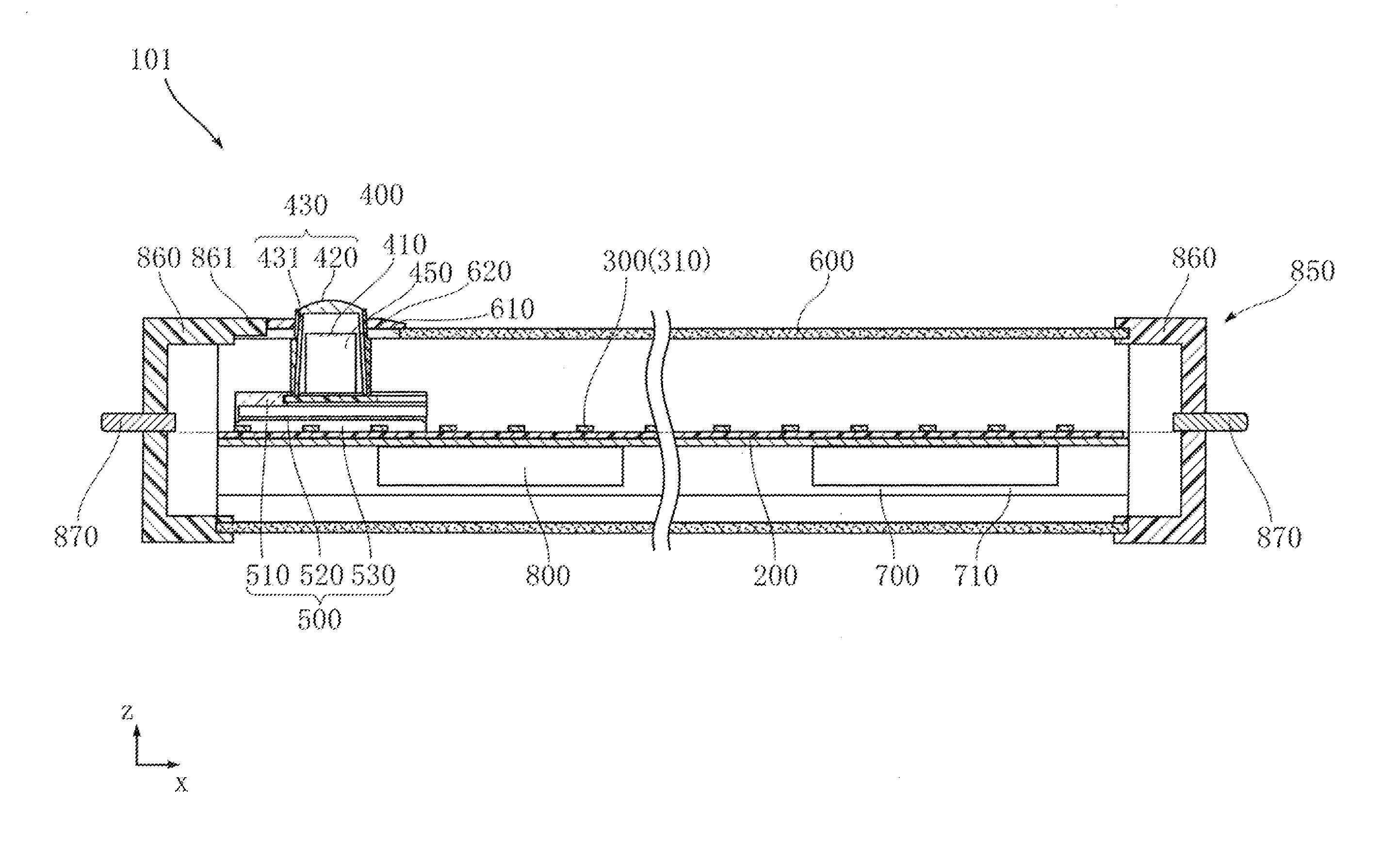
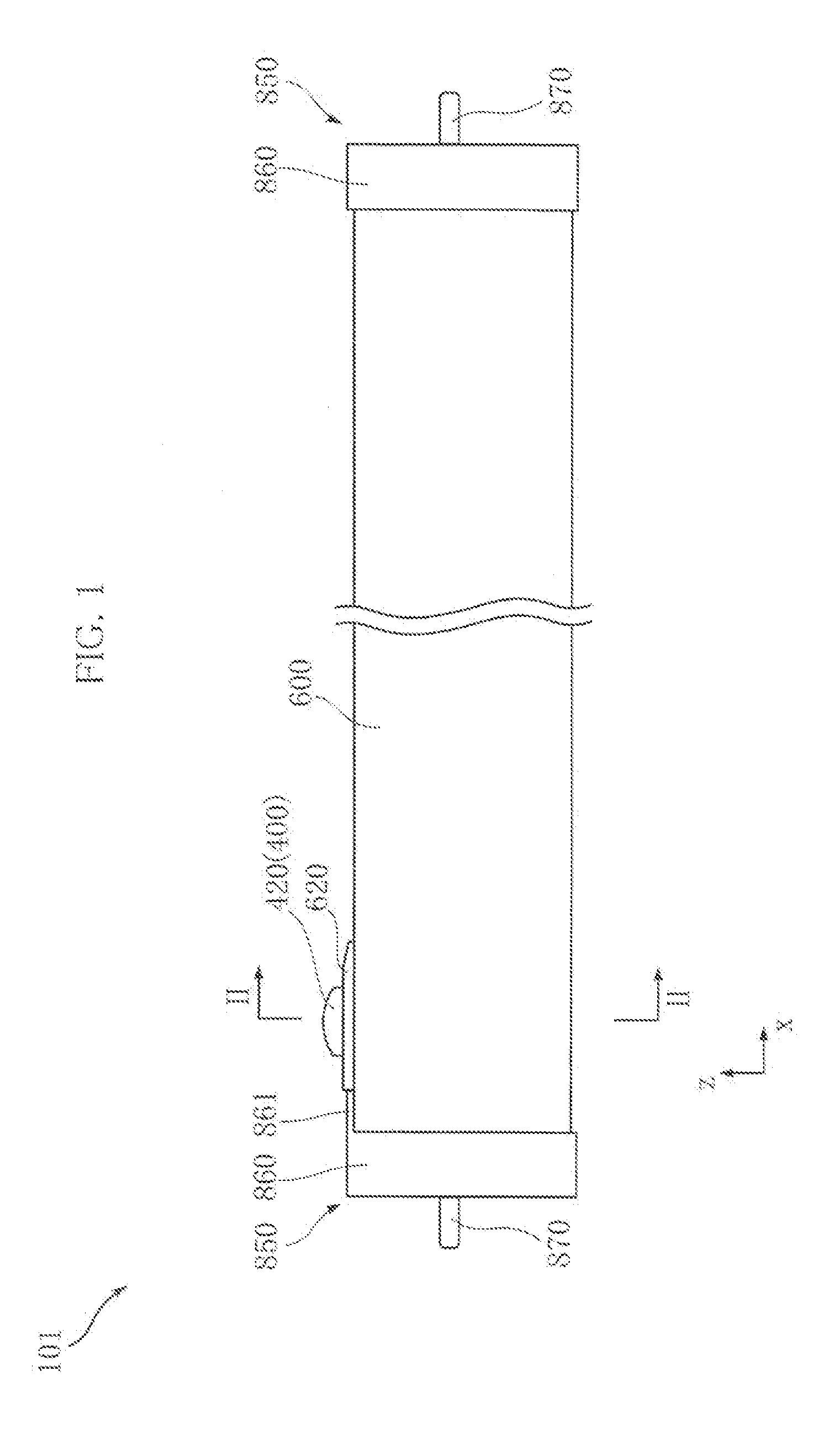
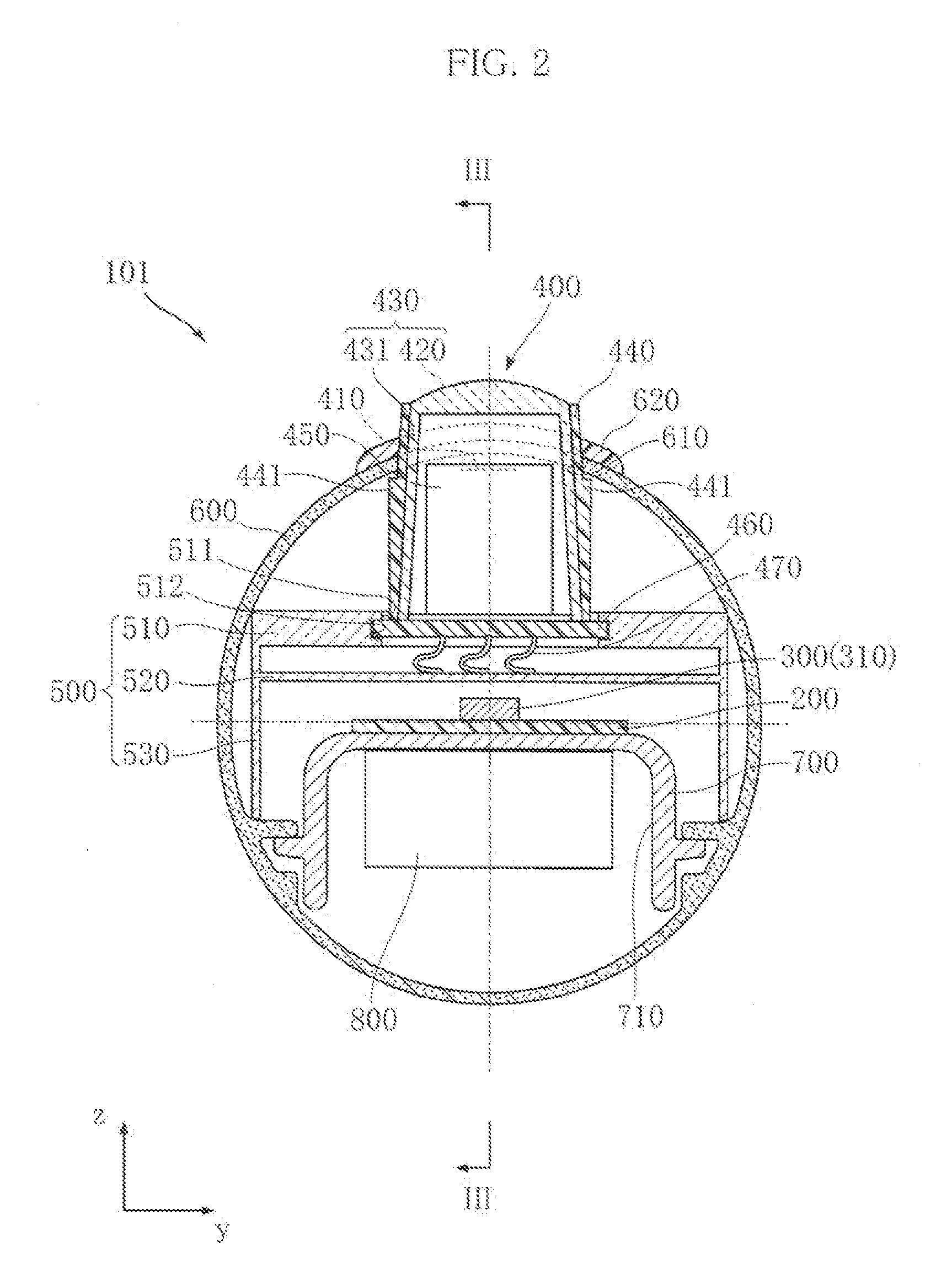
[0084]FIG. 1 through FIG. 4 show an LED lamp according to the present invention. The LED lamp 101 according to the present embodiment includes an LED substrate 200, a plurality of LED modules 300, a motion sensor unit 400, a sensor base 500, a translucent cover 600, a heat dissipater 700, a power unit 800 and a pair of caps (or bases) 850. The LED lamp 101 can be used as an alternative to a conventional straight tube fluorescent lamp, and is attachable to a light fixture for a straight tube fluorescent lamp. It should be noted here that FIG. 4 does not show the caps 850 for the sake of easier understanding. Note also, that including all of these figures and in each of the following embodiments, an optical axis direction z can be used as a reference for up-down directionality. Specifically, with reference to the optical axis direction z, an upper side represents the side closer to the floor of a room while a lower side represents the side closer to the ceiling when the fixture is in ...

second embodiment

[0108]FIG. 12 shows an LED lamp according to the present, invention. The present embodiment provides an LED lamp 102, which differs from the LED lamp 101 in the arrangement for the light shielding tube 440 of the motion sensor unit 400. In the present embodiment, a sloped surface 442 is formed on an upper end with reference to the optical axis direction z, of the light shielding tube 440. The sloped surface 442 is open upward with reference to the optical axis direction z. The sloped surface 442 has its outer edge located at a higher level than the lower edge of the condensing lens 420 with respect to the optical axis direction z. The sloped surface 442 has its lower edge aligned with the lower edge of the condensing lens 420 with respect to the optical axis direction z. Such an arrangement as the above is also capable of reducing the cases where unwanted light will hit the light receiving element 410, and therefore capable of preventing unintended actuation of the LED lamp 102.

third embodiment

[0109]FIG. 13 shows an LED lamp according to the present invention. The present embodiment provides an LED lamp 103, which differs from the LED lamps 101, 102 in the arrangement for the motion sensor unit 400. In the present embodiment, the light shielding tube 440 is bonded to the condensing lens 420, differing from the previous embodiments which include the transmissive cup 430. Such an arrangement as the above is also capable of reducing the cases where unwanted light will hit the light receiving element 410, and therefore capable of preventing unintended actuation of the LED lamp 103.


PUM


Abstract

An LED lamp includes LED chips, a translucent cover housing the LED chips, a motion sensor unit, a condensing lens, and a power unit. The motion sensor unit includes a light receiving element for light of a predetermined wavelength. The lens condenses light of the predetermined wavelength onto the light receiving element. The power unit controls the state of operation of the LED chips based on an output from the motion sensor unit. The motion sensor unit includes a light shielding member disposed to overlap the light receiving element in an optical axis direction of the condensing lens and also to surround the light receiving element as viewed in the optical axis direction. The light shielding member is made of a material having a lower light transmissivity than that of the condensing lens for a range of wavelengths including the predetermined wavelength.

Description

BACKGROUND OF THE INVENTION[0001]1. Field of the Invention[0002]The present invention relates to an LED lamp provided with a motion sensor unit.[0003]2. Description of the Related Art[0004]FIG. 16 shows a conventional LED lamp (see Patent Document 1 for example). The illustrated LED lamp 900, which can be used as an alternative to a traditional straight-tube fluorescent lamp, includes a plurality of LED (Light Emitting Diode) chips 91. The LED chips 91 are encased in a cylindrical translucent cover 94. The translucent cover 94 allows the light from the LED chips 91 to pass through while also diffusing the light. The translucent cover 94 is provided with a pair of caps 92 at its respective ends. With the caps 92 connected to an unillustrated light fixture, commercial electric power of, e.g. 100 VAC (AC voltage), is supplied to the LED lamp 900. The LED lamp 900 includes a power unit (not illustrated) which converts the 100 VAC into DC power for the LED chips 91 to turn on. The LED la...

Claims


Application Information

Patent Timeline
IPC IPC(8): H05B37/02H05B44/00
CPCF21V23/0471F21V3/02H01L2924/181H01L2224/48091H01L2224/48247F21K9/23F21Y2103/10F21Y2115/10F21K9/278H05B47/105H05B47/115H05B45/357Y02B20/40H01L2924/00012H01L2924/00014F21K9/27
Inventor NAGASHIMA, YOSHIAKIIGAKI, MASARU
Owner IRIS OHYAMA
Features
  • Generate Ideas
  • Intellectual Property
  • Life Sciences
  • Materials
  • Tech Scout
  • Unparalleled Data Quality
  • Higher Quality Content
  • 60% Fewer Hallucinations
Learn More