Customizable antenna feed structure

a feed structure and custom technology, applied in the field of custom antenna feed structures, can solve the problems of low data rate, drop calls, other performance problems, and limit the accuracy of conventional antenna structures manufactured, and achieve the effect of adjusting antenna performan

Active Publication Date: 2013-02-28
APPLE INC
View PDF7 Cites 76 Cited by
  • Summary
  • Abstract
  • Description
  • Claims
  • Application Information

AI Technical Summary

Problems solved by technology

Antennas that are inefficient or that are not tuned properly may result in dropped calls, low data rates, and other performance issues.
There are limits, however, to how accurately conventional antenna structures can be manufactured.
Many manufacturing variations are difficult or impossible to avoid.
For example, variations may arise in the size and shape of printed circuit board traces, variations may arise in the density and dielectric constant associated with printed circuit board substrates and plastic parts, and conductive structures such as metal housing parts and other metal pieces may be difficult or impossible to construct with completely repeatable dimensions.
Some parts are too expensive to manufacture with precise tolerances and other parts may need to be obtained from multiple vendors, each of which may use a different manufacturing process to produce its parts.
Manufacturing variations such as these may result in undesirable variations in antenna performance.
If the resonance frequency of an antenna is significantly different than the desired resonance frequency for the antenna, a device may need to be scrapped or reworked.

Method used


Image

  • Customizable antenna feed structure
  • Customizable antenna feed structure
  • Customizable antenna feed structure

Examples


Embodiment Construction

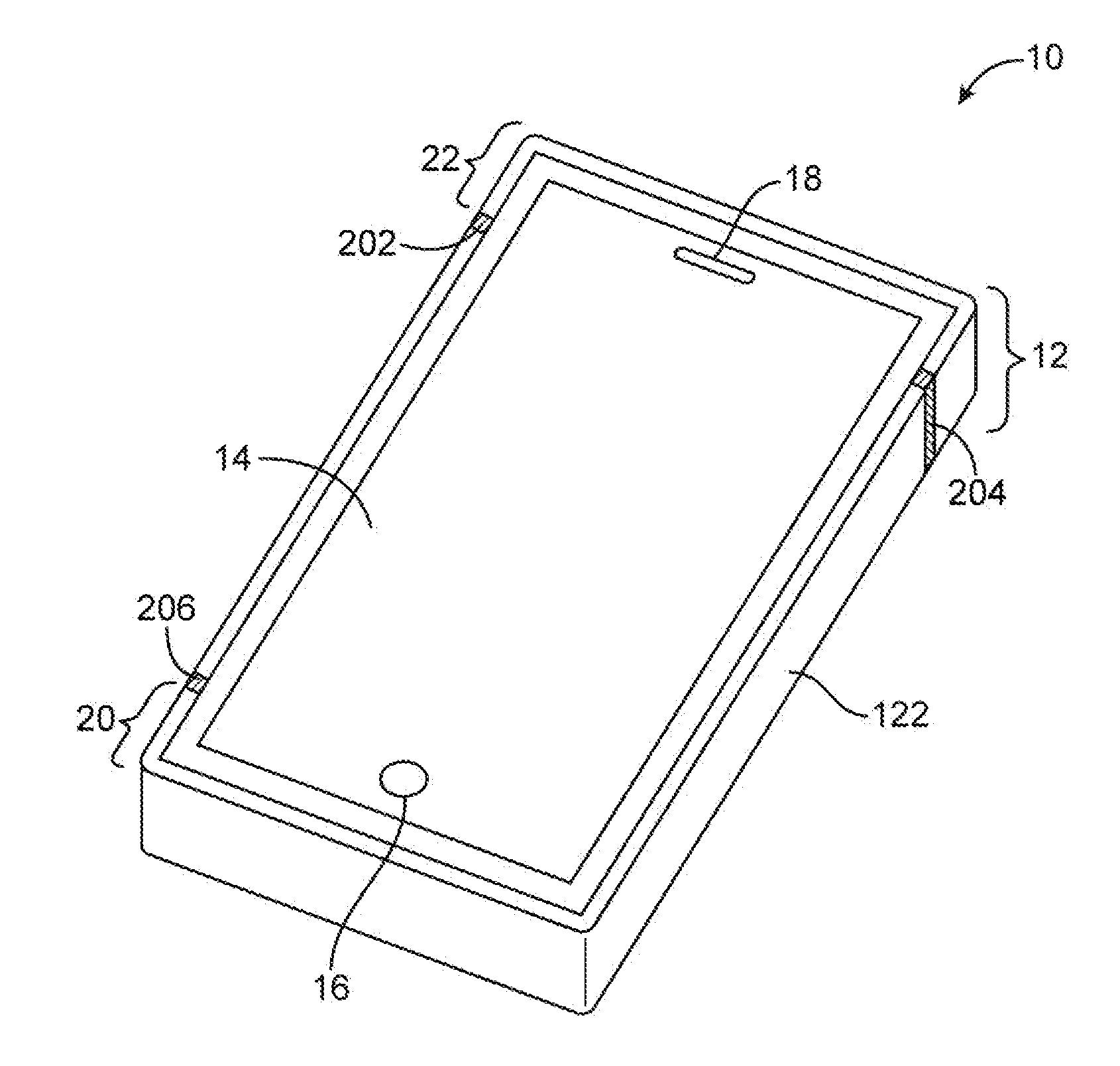
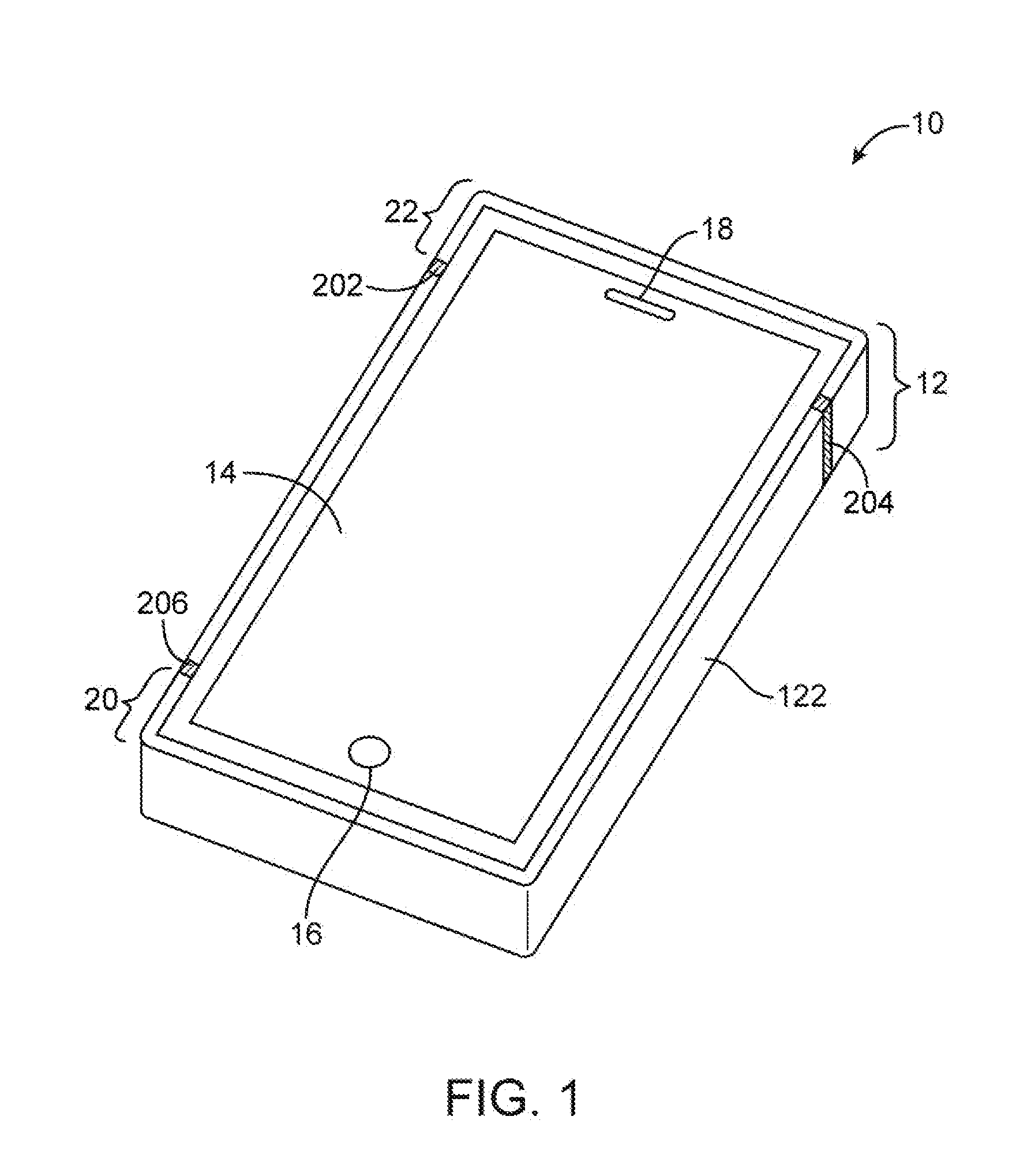
[0023]An illustrative electronic device of the type that may be provided with custom antenna structures to compensate or manufacturing variations is shown in FIG. 1. Electronic devices such as illustrative electronic device 10 of FIG. 1 may be laptop computers, tablet computers, cellular telephones, media players, other handheld and portable electronic devices, smaller devices such as wrist-watch devices, pendant devices, headphone and earpiece devices, other wearable and miniature devices, or other electronic equipment.

[0024]As shown in FIG. 1, device 10 includes housing 12. Housing 12, which is sometimes referred to as a case, may be formed of materials such as plastic, glass, ceramics, carbon-fiber composites and other fiber-based composites, metal, other materials, or a combination of these materials. Device 10 may be formed using a unibody construction in which most or all of housing 12 is formed from a single structural element (e.g., a piece of machined metal or a piece of mo...


PUM

PropertyMeasurementUnit
frequenciesaaaaaaaaaa

Abstract

Custom antenna structures may be used to compensate for manufacturing variations in electronic device antennas. An antenna may have an antenna feed and conductive structures such as portions of a peripheral conductive electronic device housing member. The custom antenna structures compensate for manufacturing variations that could potentially lead to undesired variations in antenna performance. The custom antenna structures may make customized alterations to antenna feed structures or conductive paths within an antenna. An antenna may be formed from a conductive housing member that surrounds an electronic device. The custom antenna structures may be formed from a printed circuit board with a customizable trace. The customizable trace may have a contact pad portion on the printed circuit board. The customizable trace may be customized to connect the pad to a desired one of a plurality of contacts associated with the conductive housing member to form a customized antenna feed terminal.

Description

BACKGROUND[0001]This relates generally to electronic devices, and more particularly, to electronic devices that have antennas.[0002]Electronic devices such as computers and handheld electronic devices are often provided with wireless communications capabilities. For example, electronic devices may use long-range wireless communications circuitry such as cellular telephone circuitry to communicate using cellular telephone bands. Electronic devices may use short-range wireless communications links to handle communications with nearby equipment. For example, electronic devices may communicate using the WiFi® (IEEE 802.11) bands at 2.4 GHz and 5 GHz and the Bluetooth° band at 2.4 GHz.[0003]Antenna performance can be critical to proper device operation. Antennas that are inefficient or that are not tuned properly may result in dropped calls, low data rates, and other performance issues. There are limits, however, to how accurately conventional antenna structures can be manufactured.[0004...

Claims


Application Information

Patent Timeline
Patent Type & Authority Applications(United States)
IPC IPC(8): H01Q1/50G01R31/28
CPCH01Q1/243Y10T29/49004H01Q9/145H01Q9/0421H01Q1/2283
Inventor JARVIS, DANIEL W.PASCOLINI, MATTIANICKEL, JOSHUA G.
Owner APPLE INC
Why Eureka
Try Eureka