Lighting system and method of deflection

Inactive Publication Date: 2013-02-28
SHEW LARRY N
View PDF23 Cites 45 Cited by
  • Summary
  • Abstract
  • Description
  • Claims
  • Application Information

AI Technical Summary

Benefits of technology

[0018]In yet another aspect of the present invention, a modular lighting unit is presented that contributes to a reduction in waste caused by disposing of an entire LED bulb or assembly when light emitting diodes therein burn out. The energy benefit of providing LEDs is retained while yet providing a means to replace the LEDs without requiring replacement of the entire lighting assembly. Accordingly, one or more modular LED lighting strips or modules may be provided for easy insertion and extraction from housing inserts containing the same. The housing inserts containing the modular LED light strips are forme

Problems solved by technology

Cost is one issue related to most of these conventional emergency lighting systems as they are very expensive.
Yet another issue for a conventional stand-alone emergency lighting system that may contain incandescent, fluorescent or halogen lamp and may be powered by expensive, alkaline, sealed lead battery modules is the relatively short charge time.
Many of these conventional systems are generally only designed to provide at a maximum between one to three hours of effective emergency lighting.
Not only is this approach expensive, this presents a concern for emergency generated power outages that last longer than three hours.
Yet another is

Method used


Image

  • Lighting system and method of deflection
  • Lighting system and method of deflection
  • Lighting system and method of deflection

Examples


Example

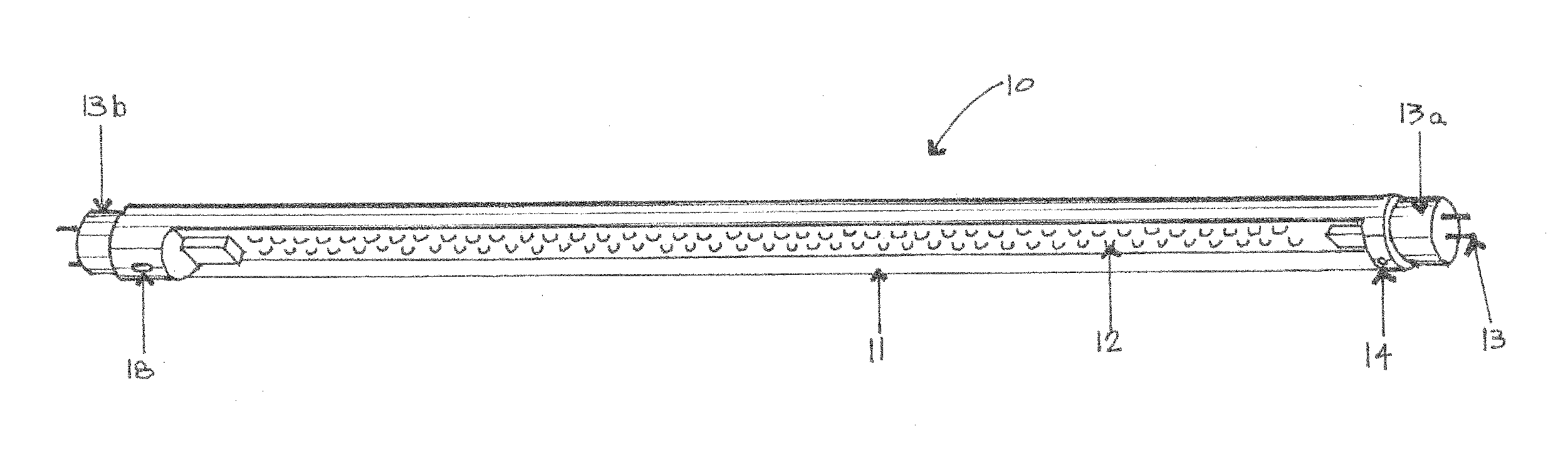
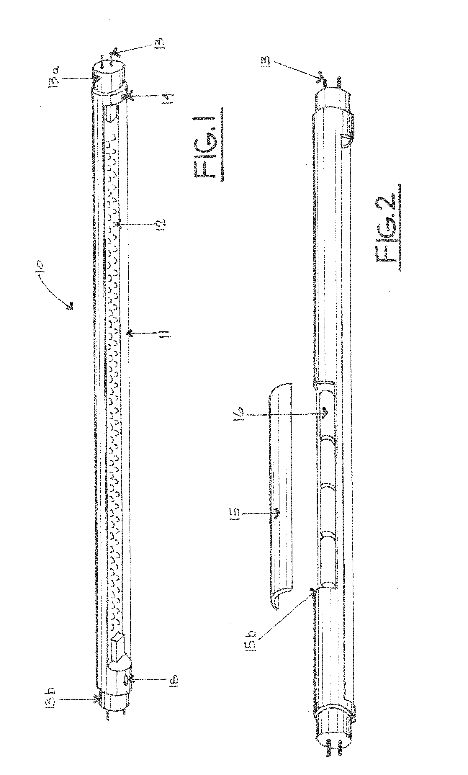
[0094]FIG. 1 is an illustration of a perspective view of a first embodiment of an emergency or backup lighting assembly 10 employing one or more light emitting diodes (LEDs). A housing or elongated tube 11 contains all internal circuitry and lighting as described below and may be manufactured as known in the art. In general, the tube 11 may be substantially similar to the housing or tube typically employed for a fluorescent light bulb, for example.

[0095]As shown in FIG. 1, an array or subassembly 12 of one or more light emitting diodes is contained within the housing 11 and may be substantially coextensive with the housing 11. The array 12 may be formed as known in the art. At least one power supply connector 13 is provided at a first end 13a for charging the batteries as explained below. In the embodiment shown in FIG. 1, a first and a second connector 13 are provided at a first end 13a and a second end 13b, respectively. A photocell switch 14 operably communicates with the LED cir...


PUM


Abstract

The present invention includes a removable lighting assembly containing: a housing; a solid state lighting unit contained within the housing and electronically communicating with the housing; and a deflector fixed about the solid state lighting unit for deflection of the light emanating therefrom.

Description

CROSS REFERENCE TO RELATED APPLICATIONS[0001]This application claims the benefit of U.S. Provisional Application Ser. No. 61 / 476,374 filed on Apr. 18, 2011. This application also claims the benefit of and is a continuation-in-part of co-pending U.S. application Ser. No. 12 / 983,227 having a filing date of Dec. 31, 2010 (which claims the benefit of U.S. Provisional Application No. 61 / 335,132 filed on Dec. 31, 2009). This application also claims the benefit of and is a continuation-in-part of co-pending U.S. application Ser. No. 13 / 417,169 having a filing date of Mar. 9, 2012 (which claims the benefit of U.S. Provisional Application No. 61 / 450,825 filed on Mar. 9, 2011). This application also claims the benefit of and is a continuation-in-part of co-pending U.S. application Ser. No. 13 / 442,843 having a filing date of Apr. 9, 2012 (which claims the benefit of U.S. Provisional Application Ser. No. 61 / 473,769 filed on Apr. 9, 2011).BACKGROUND OF THE INVENTION[0002]The present invention re...

Claims


Application Information

Patent Timeline
IPC IPC(8): F21V7/00H05B44/00
CPCH05B33/0803H02J9/065F21S9/022F21V7/0058F21V17/002F21V17/06F21Y2113/00F21Y2105/16F21V7/005F21K9/27F21K9/68Y02B20/30H05B45/3578
Inventor SHEW, LARRY N.
Owner SHEW LARRY N
Why Eureka
Try Eureka