Illumination device and illumination system

a technology of illumination device and illumination system, which is applied in the direction of semiconductor devices for light sources, lighting and heating apparatus, and light support devices, etc., can solve the problems of inability to arrange light emitting units, restricted arrangement of light emitting units, and poor workability, so as to improve workability, reduce the restriction in arrangement, and eliminate the restriction in arrangement

Inactive Publication Date: 2013-02-28
PANASONIC INTELLECTUAL PROPERTY MANAGEMENT CO LTD
View PDF14 Cites 7 Cited by
  • Summary
  • Abstract
  • Description
  • Claims
  • Application Information

AI Technical Summary

Benefits of technology

[0005]In view of the above, the present invention provides an illumination device capable of enhancing the workability when electrically connecting the illumination device to an external device and capable of reducing the restriction in arrangement generated during the connection and eventually increasing the degree of freedom in arrangement, and an illumination system using the same.
[0015]In the present invention, the connection terminal, to which the external conductor is connected, is arrange inward of the outer peripheral end of the mounting unit. The clearance for passing the external conductor therethrough is formed between the light source unit and the mounting unit. Thus there is provided a space for accommodating the external conductor. Accordingly, even if an additional space is needed when the illumination device is electrically connected to the external device by, e.g., bending the external conductor or by using the external conductor differing in shape, it is possible to secure the additional space and to enhance the workability. In addition, it is possible to eliminate the restriction in arrangement in securing the space for accommodation of the external conductor. It is also possible to reduce the restriction in arrangement caused by the electric connection of the illumination device to the external device. This assists in increasing the degree of freedom in arrangement.

Problems solved by technology

As a result, even if the external conductor is bent or the external conductor differing in shape is used in conformity with the arrangement of the light emitting units, it is sometimes the case that the workability grows worse due to the insufficient space.
The arrangement of the light emitting units is restricted if an attempt is made to secure a sufficient space.
It is therefore impossible to arrange the light emitting units with no gap left therebetween.
This reduces the degree of freedom in arranging the light emitting units.

Method used


Image

  • Illumination device and illumination system
  • Illumination device and illumination system
  • Illumination device and illumination system

Examples


Embodiment Construction

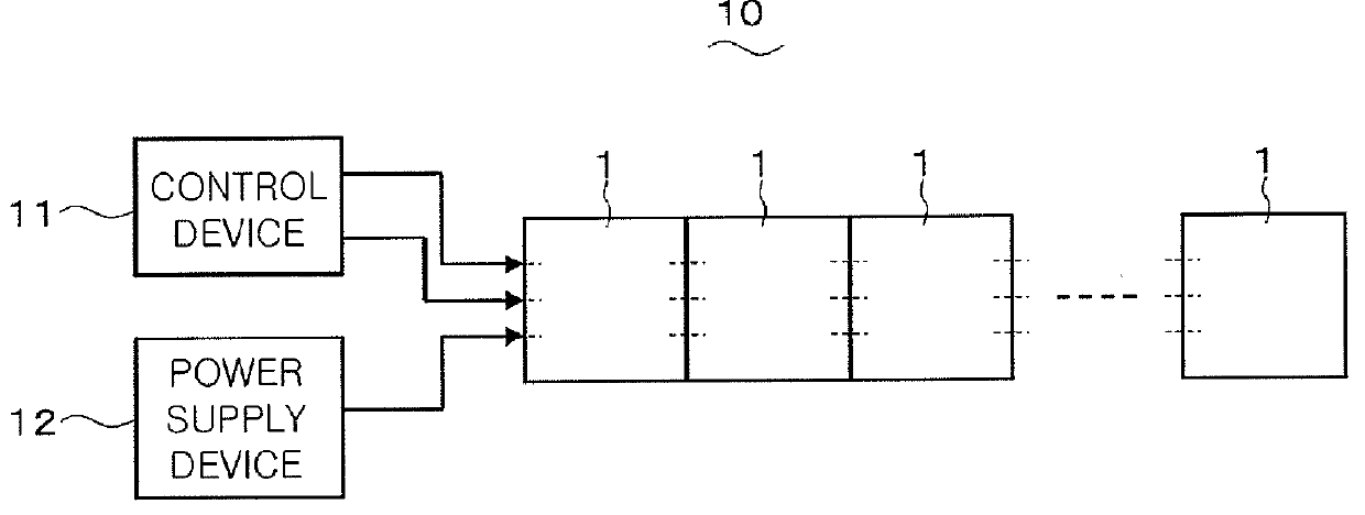
[0024]An illumination device according to an embodiment of the present invention and an illumination system using the same will now be described with reference to the accompanying drawings which form a part hereof. FIG. 1 shows the configuration of an illumination system including a plurality of illumination devices according to the present embodiment.

[0025]The illumination devices 1 according to the present embodiment are configured so that they can be electrically connected to one another. In the illumination system 10 shown in FIG. 1, the illumination devices 1 are arranged side by side in a row and are electrically connected to one another. The illumination system 10 further includes a control device 11 and a power supply device 12, both of which are electrically connected to one of the illumination devices 1 arranged at one end.

[0026]The control device 11 transmits a control signal for the control of the illumination devices 1 to the target illumination devices 1 through two tr...


PUM


Abstract

An illumination device includes a light source unit having a light emitting panel, and a mounting unit attached to a non-light-emission surface of the light source unit and provided with a circuit board for controlling energization of the light emitting panel. The mounting unit includes a connection terminal to which an external conductor for electrically interconnecting the circuit board and an external device is connected. The connection terminal is arranged inward of an outer peripheral end of a surface of the mounting unit to which the light source unit is attached. A clearance for passing the external conductor therethrough is formed between the light source unit and the mounting unit in a state that the external conductor is connected to the connection terminal and the mounting unit is attached to the light source unit.

Description

FIELD OF THE INVENTION[0001]The present invention relates to an illumination device in which a light emitting panel is used as a light source and an illumination system using the same.BACKGROUND OF THE INVENTION[0002]In the past, there is known an illumination system including a plurality of tile-shaped flat light emitting units (hereinafter referred to as “light emitting units”). In this illumination system, the light emitting units are arranged in a grid shape to adjoin to one another. The adjoining light emitting units are electrically connected to each other through contact points arranged in the mutually adjoining edges of the light emitting units. Electric power is fed from one of the light emitting units to the other via the contact points (see, e.g., Japanese Application Publication No. 2007-536708).[0003]In the light emitting units of this kind, an external conductor such as a lead wire or the like is used to electrically interconnect the adjoining light emitting units. The...

Claims


Application Information

Patent Timeline
Patent Type & Authority Applications(United States)
IPC IPC(8): F21V33/00
CPCF21V27/00F21S2/00F21V21/02F21V23/002F21V21/03F21V23/06F21Y2105/008F21S2/005F21V23/006F21Y2105/00F21Y2115/15
Inventor KOTERA, RYUSUKEKAWACHI, HIDEHARU
Owner PANASONIC INTELLECTUAL PROPERTY MANAGEMENT CO LTD
Why Eureka
Try Eureka