Controller for a clockwork mechanism, and corresponding method

a technology of clockwork mechanism and controller, which is applied in the field of mechanical watches, can solve the problems of relatively complicated electronics, adverse effects of position change on the running of the wristwatch, etc., and achieve the effects of reducing the ohmic resistance of the switch, reducing the power consumption of the electronic circuit, and high efficiency

Active Publication Date: 2013-02-28
TEAM SMARTFISH
View PDF4 Cites 44 Cited by
  • Summary
  • Abstract
  • Description
  • Claims
  • Application Information

AI Technical Summary

Benefits of technology

[0012]It is another aim to make available a new regulating element or auxiliary regulating element for a mechanical clockwork movement that can be integrated into an existing mechanical clockwork movement with minimal changes.
[0025]The transistors for adjusting the impedance at the output of the spiral hairspring are only switched on or connected when the voltage induced by the spiral hairspring is lower than a predetermined threshold or when the current generated by the spiral hairspring is lower than a predetermined threshold. It is thus possible in this way to reduce energy losses.

Problems solved by technology

One disadvantage of mechanical watches by comparison with electronic watches is that the running of a wristwatch is adversely affected by changes in position, fluctuating temperatures, magnetism, dust, irregular winding-up and oils.
The clockwork from EP848842 requires however a relatively complicated electronics, a generator supplying the energy needed for operating the electronics, as well as a relatively large space for integrating the systems.
A further disadvantage of such a timepiece movement is that the forces and torques are different from those of a mechanical clockwork movement, so that the entire clockwork movement needs to be adapted.

Method used


Image

  • Controller for a clockwork mechanism, and corresponding method
  • Controller for a clockwork mechanism, and corresponding method
  • Controller for a clockwork mechanism, and corresponding method

Examples


Embodiment Construction

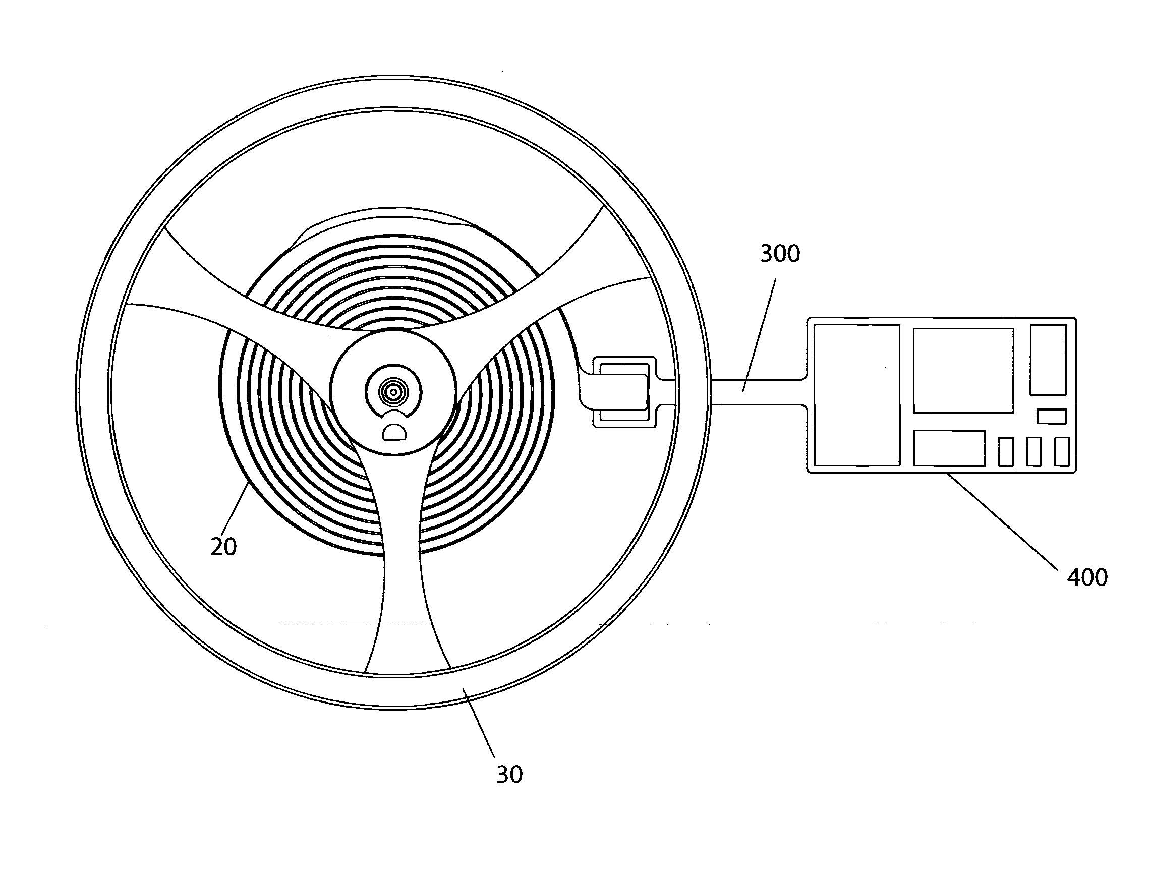
[0038]A regulating element according to the invention comprises a conventional balance 30, a piezoelectric spiral hairspring 20 (FIGS. 4, 5a and 5b) and an electronic circuit 40 for controlling the precision of a mechanical clockwork movement with a piezo electric hairspring. This regulating element is connected in a conventional manner through an escapement (not represented) with the geartrain of a mechanical clockwork movement supplying the required energy and whose running can thus be controlled.

[0039]The piezoelectric spiral hairspring 20 consists of a piezoelectric material or of a material at least coated with a piezoelectric layer, preferably of a Semiconductor material (for example silicon) 200, which is at least partly (FIG. 5a and FIG. 5b) coated with a piezoelectric material 202-207 and an electrode 208. Number 202 refers to a seeding layer, 203 and 204 are intermediary layers of AlGaN resp. AlN, 205 is a semiconductor layer (for example of GaN), 206 is an intermediary la...


PUM


Abstract

Controller for a clockwork mechanism, having the following components: a balance wheel; a piezoelectric helical spring (20); an electronic circuit for coordinating the stiffness of the piezoelectric helical spring (20); characterized in that the electronic circuit has a plurality of capacitors which can be switched individually (222, 224, 226, 228).

Description

RELATED APPLICATIONS[0001]This application is a continuation of PCT / EP2011 / 056484, filed Apr. 21, 2011, which claims priority to 2010CH-0580, filed Apr. 21, 2010, 2010CH-0692, filed May 6, 2010, 2010CH-1298, filed Aug. 12, 2010, 2010CH-1440, filed Sep. 7, 2010, 2010CH-1454, filed Sep. 10, 2010, 2010CH-1537, filed Sep. 23, 2010, 2010CH-1824, filed Nov. 2, 2010, 2010CH-1931, filed Nov. 18, 2010, 2010CH-2132, filed Dec. 21, 2010 and 2011CH-0322, filed Feb. 24, 2011, the entire contents of which are hereby incorporated by reference.TECHNICAL FIELD[0002]The invention relates to a mechanical watch, whose regulating element or controller comprises a balance, a spiral hairspring and an electronic circuit with a quartz oscillator.BACKGROUND OF THE INVENTION[0003]Mechanical watches are powered by a mainspring. This spring is the motor of mechanical watches: it is wound up either manually or through the automatic winding-up mechanism when the watch is worn on the wrist and thus stores energy. ...

Claims


Application Information

Patent Timeline
Patent Type & Authority Applications(United States)
IPC IPC(8): G04B17/06G04C3/04
CPCG04B17/066G04C3/047G04B17/227
Inventor SCHAFROTH, KONRAD
Owner TEAM SMARTFISH
Why Eureka
Try Eureka