Dynamic apertured waveguide for near-eye display

a waveguide and waveguide technology, applied in the field of plate-shaped waveguide systems, can solve the problems of limiting the number of wavelengths or the different angles through which image information can be effectively transmitted, chromatic aberration, and limited waveguide displays, so as to achieve the effect of enhancing image uniformity with the eyebox pupil and regulating diffraction efficiency

Active Publication Date: 2013-02-28
VUZIX
View PDF8 Cites 175 Cited by
  • Summary
  • Abstract
  • Description
  • Claims
  • Application Information

AI Technical Summary

Benefits of technology

[0008]The electronic controls of the controllable output aperture can be patterned for variously activating different segments of the output aperture, i.e., different sections of the transformable grating structure. That is, the different segments of the output aperture can be made individually addressable so that one or more aperture segments can be switched to an active state while other aperture segments remain in a passive state. The electronic controls can also provide for various intermediate states in which the refractive index difference between the transformable grating structure and its contiguous mating optic can be raised or lowered to regulate diffraction efficiency. Moreover, the electronic controls can be synchronized with the injection of various image-bearing beams such as from a scanning optic so that the beams can be ejected through different portions of the output aperture and for different durations. For example, the higher incident angle beams can be ejected through one segment of the output aperture a...

Problems solved by technology

The waveguide displays are often limited to the use of monochromatic light in which the virtual images are formed in a single color.
Conventional diffractive optics tend to diffract different wavelengths through different angles, creating chromatic aberrations.
Multiple waveguides (e.g., stacked waveguides) or more complex diffractive optics can be used to mitigate these aberrations but the solutions tend to limit the number of wavelengths or the different angles through which the image information can be effectively transmitted.
The effective exit pupil size within which the vi...

Method used


Image

  • Dynamic apertured waveguide for near-eye display
  • Dynamic apertured waveguide for near-eye display
  • Dynamic apertured waveguide for near-eye display

Examples


Embodiment Construction

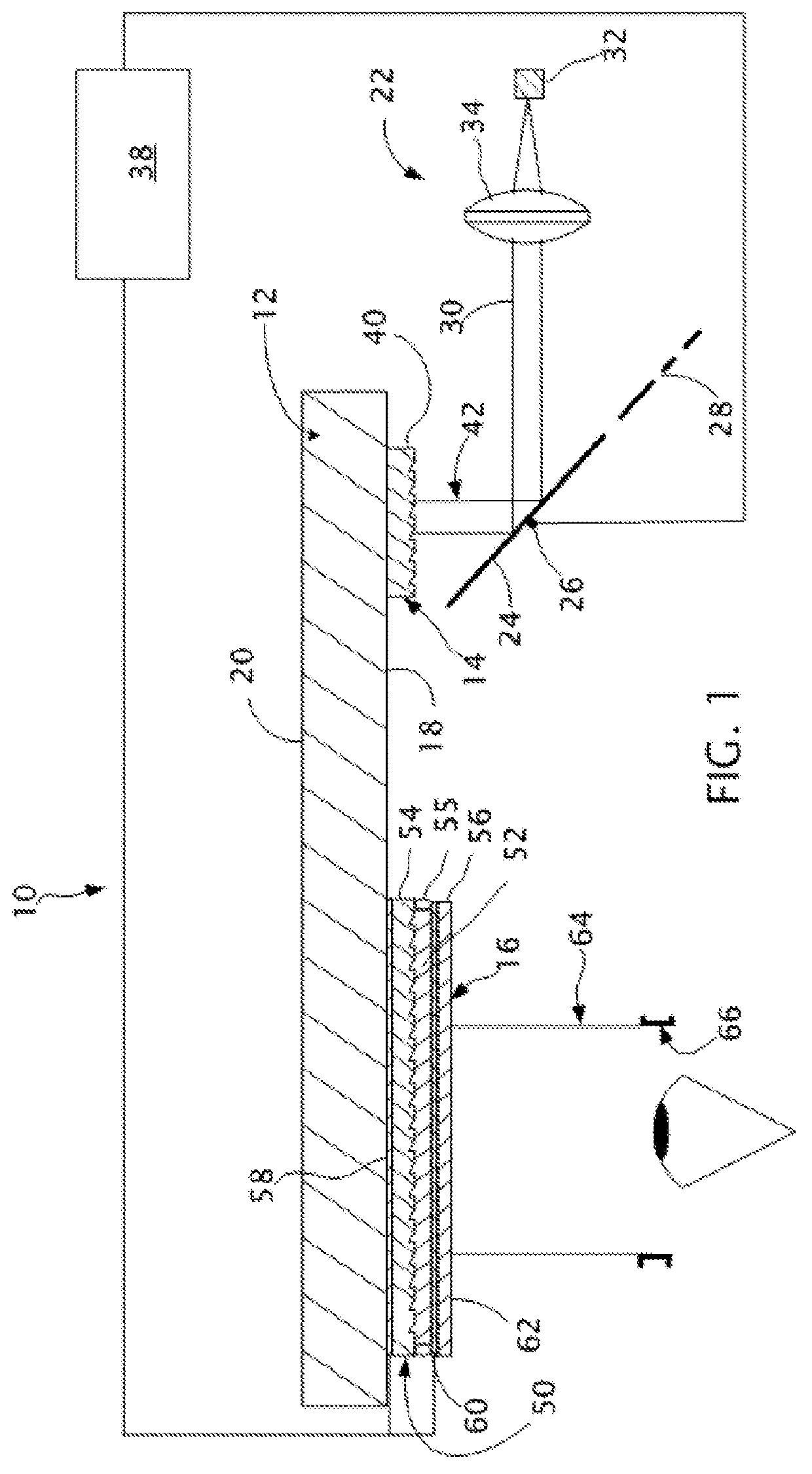
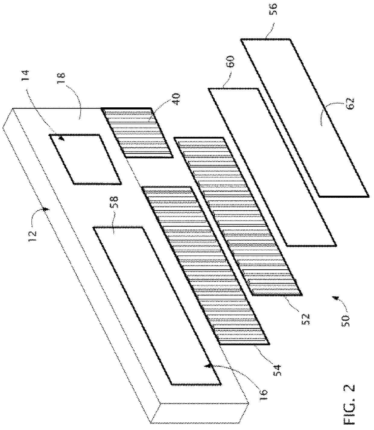
[0019]With reference to FIG. 1, a near-eye display 10 of a type including a plate-shaped waveguide 12 also shown in the view of FIG. 2 has an input aperture 14 and a controllable output aperture 16. The plate-shaped waveguide 12 is preferably a transmissive plate having an inside surface 18 (facing the users eye) and an outside surface 20 (facing the ambient environment), with both the inside and outside surfaces 18 and 20 being exposed to air or another lower refractive index medium.

[0020]The plate-shaped waveguide 12 can be made of various transmissive optical materials, such as BK7 glass having a nominal refractive index of 1.527, and has dimensions for transmitting light to a position within the field of view of a user from an off axis position at which the light can be injected. For example, the plate-shaped waveguide can have a length of approximately 60 millimeters for reaching the eye position, a height of approximately 30 millimeters allowing for a second dimension of the i...


PUM


Abstract

A near-eye display of a type having an image generator for generating a succession of angularly related beams and waveguide for propagating the angularly related beams to an eyebox within which a virtual image is visible includes a controllable output aperture for such purposes as reconstructing a better defined pupil within the eyebox while also preserving the possibility for viewing the ambient environment from the eyebox through the controllable output aperture.

Description

TECHNICAL FIELD[0001]The present invention relates to plate-shaped waveguide systems for transmitting angularly encoded image information particularly for near-eye displays and to controllable output apertures for such purposes as optimizing viewing conditions.BACKGROUND OF THE INVENTION[0002]Compact near-eye displays often use plate-shaped (usually planar) waveguides for transmitting angular image information to users' eyes as virtual images from image sources located out of the user's line of sight. The image information is generally input near one end of the waveguides and is output near another end of the waveguides. The image information propagates along the waveguides as a plurality of angularly related beams that are internally reflected along the waveguide. Diffractive optics are often used for injecting the image information into the waveguides through a first range of incidence angles that are internally reflected by the waveguides as well as for ejecting the image informa...

Claims


Application Information

Patent Timeline
IPC IPC(8): G02B6/34
CPCG02B6/34G02B2027/0123G02B27/01G02B6/4298G02B27/0081G02B27/4272
Inventor TRAVERS, PAUL J.SCHULTZ, ROBERT J.
Owner VUZIX
Why Eureka
Try Eureka