
Air valve for energy storage device and energy storage device including the same

a technology of energy storage device and air valve, which is applied in the direction of valve operating means/release devices, cell components, cell component details, etc., can solve the problems of large explosion, short life, and relative long life, and achieve the effect of minimizing the volume of the air valve, simple structure and smooth gas discharg

Inactive Publication Date: 2013-02-28
SAMSUNG ELECTRO MECHANICS CO LTD
View PDF2 Cites 10 Cited by
  • Summary
  • Abstract
  • Description
  • Claims
  • Application Information

AI Technical Summary

Benefits of technology

The present invention provides an air valve for an energy storage device that can smoothly release gases from the device while keeping the size of the air valve simple. The energy storage device includes the air valve, which helps to minimize the volume of the device and makes it more efficient in terms of energy storage and utilization. Overall, the technical effects of the patent text revolve around minimizing the size of the air valve while ensuring efficient gas discharge from the energy storage device.

Problems solved by technology

Meanwhile, the secondary battery may have disadvantages in that time consumed to perform charging and discharging is relatively long, output voltage is as low as about 3V, a lifespan is short, a risk of explosion is large, or the like, such that the secondary battery has a limitation in applications.
Therefore, when these gases are not appropriately discharged, a case of the energy storage device is ruptured, such that the energy storage device may not be used anymore or in extreme cases, may be exploded.
The supercapacitor does not completely solve problems such as energy density, resistance, or the like, such that it is difficult to smoothly commercialize the supercapacitor.
When the method is used, maintenance costs may be increased and maintenance may be complicated since the metal thin film needs to be replaced each time the metal thin film is ruptured.

Method used


Image

  • Air valve for energy storage device and energy storage device including the same
  • Air valve for energy storage device and energy storage device including the same
  • Air valve for energy storage device and energy storage device including the same

Examples


Embodiment Construction

[0025]Hereinafter, exemplary embodiments of the present invention in which objects of the present invention may be specifically implemented will be described with reference to the accompanying drawings. In exemplary embodiments of the present invention, the same terms and reference numerals will be used to describe the same components. Therefore, an additional description for the same component will be omitted below.

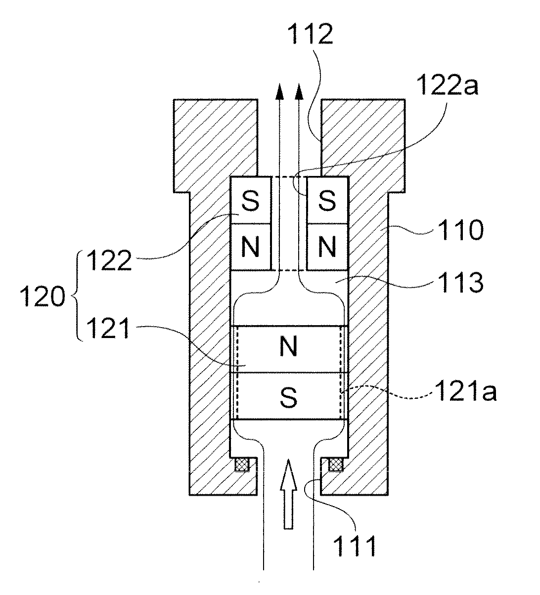
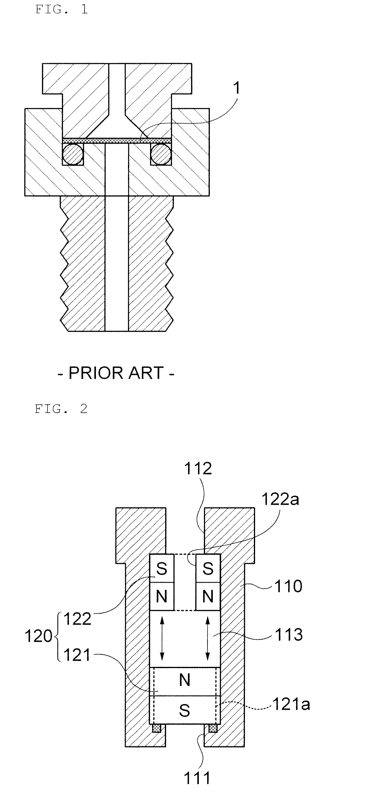
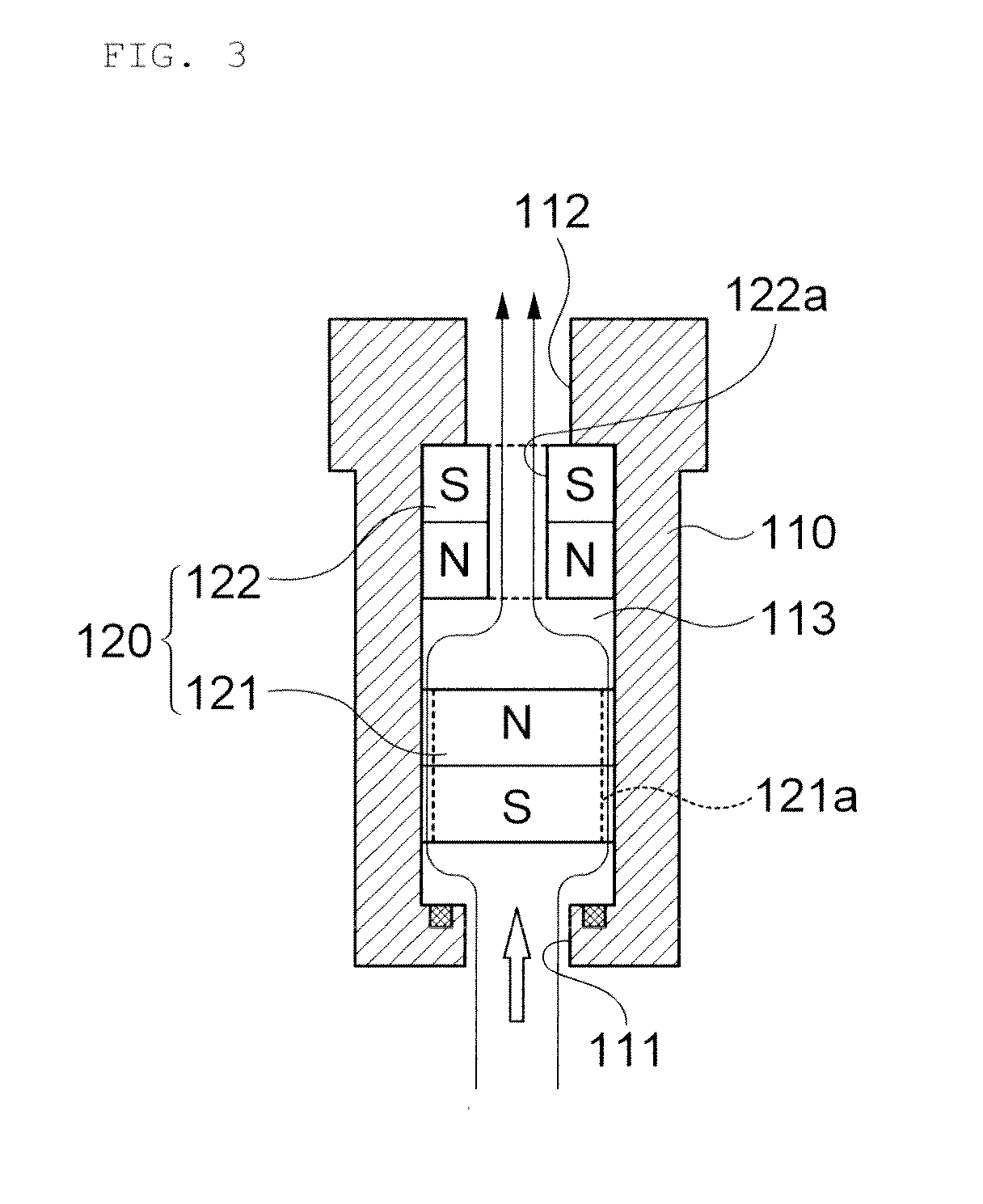
[0026]An air valve for an energy storage device and an energy storage device including the same according to an exemplary embodiment of the present invention will be described in more detail with reference to FIGS. 2 and 3.

[0027]FIG. 2 is a cross-sectional view schematically showing an air valve for an energy storage device according to an exemplary embodiment of the present invention and FIG. 3 is a cross-sectional view showing a case in which gases are discharged to the outside by communicating an inlet with an outlet by moving a moving magnet upwardly when a gas press...


PUM

PropertyMeasurementUnit
output voltageaaaaaaaaaa
gas pressureaaaaaaaaaa
pressureaaaaaaaaaa

Abstract

Disclosed herein is an air valve for an energy storage device, including: a valve body mounted in a gas vent of an energy storage device and having a passage for discharging gases within the gas vent to the outside; and a plurality of magnets mounted within the passage to apply repulsion force to one another so as to block the gas vent from the outside by the repulsion force and communicate the gas vent with the outside when a gas pressure within the gas vent is larger than the repulsion force, thereby discharging gases. By this configuration, exemplary embodiments of the present invention can configure the air valve with the simple structure capable of smoothly discharging gases generated from the energy storage device while minimizing a volume of the air valve and being semi-permanently used while minimizing a mechanical configuration of the air valve.

Description

CROSS REFERENCE(S) TO RELATED APPLICATIONS[0001]This application claims the benefit under 35 U.S.C. Section 119 of Korean Patent Application Ser. No. 10-2011-0086531, entitled “Air Valve For Energy Storage Device And Energy Storage Device Including The Same” filed on Aug. 29, 2011, which is hereby incorporated by reference in its entirety into this application.BACKGROUND OF THE INVENTION[0002]1. Technical Field[0003]The present invention relates to an air valve for an energy storage device and an energy storage device including the same, and more particularly, to an air valve for an energy storage device and an energy storage device including the same capable of smoothly discharging gases generated from the energy storage device while minimizing a volume of the air valve with a simple structure and being semi-permanently used while minimizing a mechanical configuration thereof.[0004]2. Description of the Related Art[0005]Recently, with the technology development of electric and elec...

Claims


Application Information

Patent Timeline
Patent Type & Authority Applications(United States)
IPC IPC(8): H01M2/12F16K31/08H01G9/004F16K17/02
CPCF16K31/084F16K17/02H01M2/1205H01G11/80Y02E60/13H01G11/18H01M50/308Y02E60/10Y10T137/7904
Inventor NOH, JUNG EUNPARK, SUNG YEOLCHO, YEONG SU
Owner SAMSUNG ELECTRO MECHANICS CO LTD
Learn More