Walking assist device

a technology of walking assist and wearable parts, which is applied in the direction of battery maintenance/servicing, manufacturing tools, and primary cell maintenance/servicing, etc., can solve the problems of reducing the electric power supplied to the actuator, restricting the ability of the walking assist device, and reducing the use effect of batteries

Inactive Publication Date: 2013-02-28
TOYOTA JIDOSHA KK
View PDF5 Cites 17 Cited by
  • Summary
  • Abstract
  • Description
  • Claims
  • Application Information

AI Technical Summary

Benefits of technology

[0013]The “period in which the sound leg is making contact with the ground” includes a both legs standing period and the one leg standing period of the sound leg. The one leg standing period of the sound leg corresponds to an idling leg period of the wearing leg. It is preferable that the leg attachment has the ground contact sensor and the controller is configured to change the battery during the idling leg period of the wearing leg. The “idling leg period of the wearing leg” is a part of the “period in which the sound leg is making contact with the ground”. In the idling leg period of the wearing leg, large torque is not required because the assist device does not have to support the weight of the user. Therefore, the idling leg period of the wearing leg is a favorable period to change the battery.
[0014]The first battery and the second battery may be physically independent from each other. Alternatively, the first battery and the second battery may constitute a battery cell group, a part of which can be shared in common as described below. That is, the first battery may be composed of a plurality of battery cells being connected, and the second battery may correspond to a battery in which at least one battery cell is electrically separated from the first battery. When one battery is composed of a plurality of connected battery cells, a compact battery with good performance can be realized. On the other hand, as for the battery composed of the plurality of battery cells, malfunction of one battery cell can cause an output voltage of the whole battery to decrease. Thus, the battery composed of the plurality of battery cells can be used efficiently if the battery is configured capable of electrically separating the battery cell with malfunction. That is, it is preferable that the controller of the assist device is configured to electrically separate the battery cell with malfunction from the battery composed of the plurality of connected battery cells (the first battery) while the sound leg (the other leg mentioned earlier) is making contact with the ground. The battery in which the battery cell with malfunction is electrically separated corresponds to the second battery.
[0015]It is further preferable that the above assist device has a third battery which compensates for a temporary voltage decrease upon changing a battery. The third battery is independent from the first battery and the second battery. A capacity of the third battery can be smaller than a capacity of the first battery, since the third battery simply compensates for the temporary voltage decrease. In this case, the controller connects the third battery to the actuator as one of power sources while the power source of the actuator is changed from the first battery to the second battery. A small size battery (the third battery) compensates for the temporary voltage decrease, and supplies a sufficient electric power to the actuator.
[0017]As described above, the wearable walking assist device which the present description discloses makes it possible to use batteries efficiently by changing the battery to be used among the plurality of batteries. Also, the wearable walking assist device of the present description does not influence the capability to assist walking even if the voltage temporarily decreases when changing the battery.

Problems solved by technology

As the technique in patent document 1 discloses, restricting the output of the actuator leads to restricting a capability of the walking assist device.
There is a possibility that the actuator fails to apply sufficient torque to support the weight of the user in a case that electric power supplied for the actuator decreases while the walking assist device is supporting the weight of the user.

Method used


Image

  • Walking assist device
  • Walking assist device
  • Walking assist device

Examples


Embodiment Construction

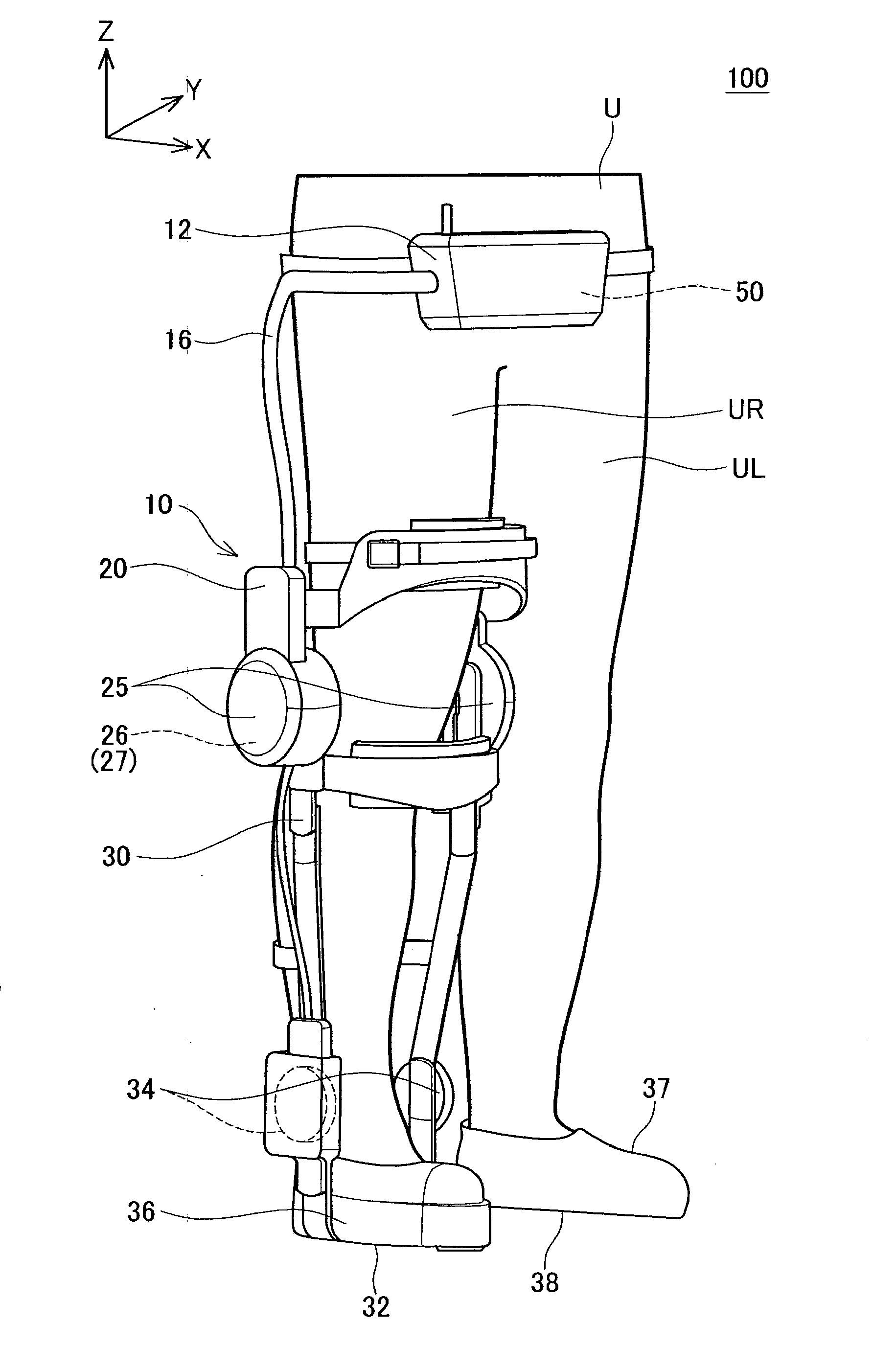
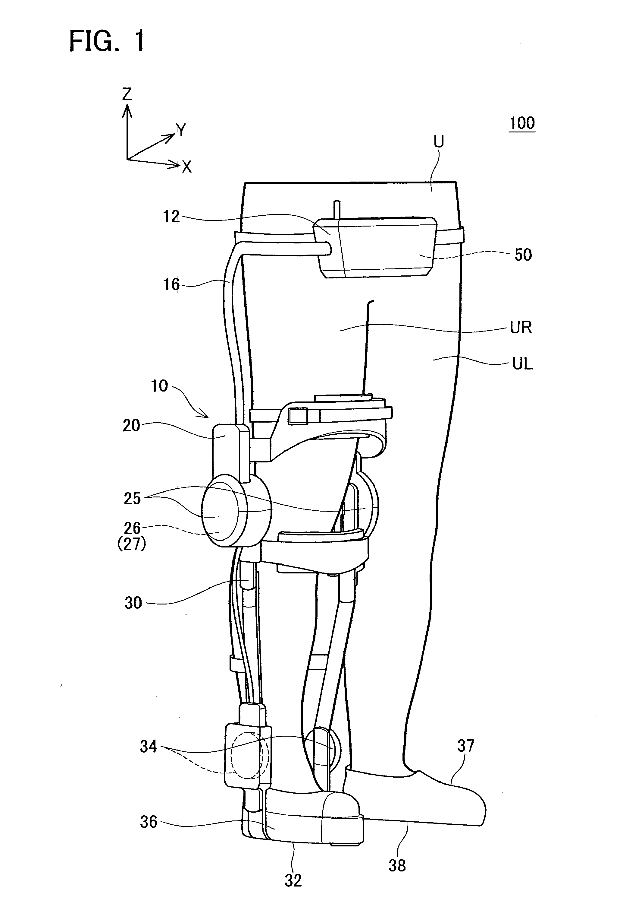
[0023]FIG. 1 shows a schematic view of a walking assist device 100 in a first embodiment. The waling assist device 100 mainly comprises a leg attachment 10 which is attached to a right leg (UR) of a user U and a controller 12 which controls the leg attachment 10. Note that the controller 12 has a built-in battery 50. In the present embodiment, assume that the user U is a patient whose left leg UL is sound but right leg UR is impossible to move freely. Since the left leg UL is sound, the leg attachment 10 is attached only to the right leg UR. The right leg UR corresponds to a wearing leg, and the left leg UL corresponds to a sound leg.

[0024]A coordinate system will be described before describing the walking assist device 100. As shown in FIG. 1, an x-axis is set in a forward direction of the user U, a y-axis is set in a lateral direction of the user U, and a z-axis is set in a vertically upward direction. In general, in a technical field of robots, an axis (x-axis) extending in a fro...


PUM


Abstract

Provided is a walking assist device capable of changing a battery to be used without decreasing a capability to assist walking A walking assist device comprises a leg attachment, a battery, and a controller. The leg attachment has an actuator for applying torque on a joint of one leg of a user. The battery supplies electric power to the actuator. The battery (a first battery) is configured by a plurality of battery cells being connected. A battery in which at least one battery cell is electrically separated from the first battery corresponds to a second battery. The controller changes a power source of the actuator from the first battery to the second battery while the other leg is making contact with ground.

Description

CROSS-REFERENCE TO RELATED APPLICATION[0001]This is a Continuation of International Application No. PCT / JP2010 / 070976 filed on Nov. 25, 2010, the disclosure of which is hereby incorporated by reference herein in its entirety.TECHNICAL FIELD[0002]The present invention relates to a wearable walking assist device that assists a user in walking.BACKGROUND ART[0003]A wearable walking assist device is being developed. This type of walking assist device is attached to a user's leg. An actuator of the walking assist device applies torque on a joint of the user's leg in response to walking action. In the following description, the wearable walking assist device may be simply referred to as an “assist device”. It is preferable that the wearable walking assist device does not restrict user's range of activity. Therefore, the assist device has a battery that supplies electric power to the actuator.[0004]Usable life of the assist device is determined by duration of the battery. That is, it is im...

Claims


Application Information

Patent Timeline
Patent Type & Authority Applications(United States)
IPC IPC(8): A61H1/02
CPCA61H1/024A61H1/0266A61H3/00B25J9/0006H01M6/5016H01M2220/30A61H2201/0173A61H2201/165B25J19/005H01M10/482Y02E60/10
Inventor KONISHI, KENTA
Owner TOYOTA JIDOSHA KK
Why Eureka
Try Eureka