Variable compression ratio engine control apparatus

a control apparatus and compression ratio technology, applied in the direction of engine controllers, machines/engines, electric control, etc., can solve the problems of insufficient increase of engine operating performance, inability to achieve ignition and combustion satisfactorily, and prescribed engine braking, etc., to suppress pumping loss, reduce engine compression ratio, and effectively recover energy

Inactive Publication Date: 2013-03-07
NISSAN MOTOR CO LTD
View PDF5 Cites 34 Cited by
  • Summary
  • Abstract
  • Description
  • Claims
  • Application Information

AI Technical Summary

Benefits of technology

[0007]For example, during a deceleration operating state in which a fuel cut is executed, a prescribed engine braking occurs due to a pumping loss. In such a case, reducing the engine compression ratio suppresses a compression pressure and suppresses the pumping loss. Thus, by executing a control that utilizes an amount of energy corresponding to the suppressed pumping loss to regeneratively operate, for example, an alternator (generator) so as to generate electric power, a prescribed engine braking can be accomplished while effectively recovering energy that would otherwise be wasted, thereby improving fuel efficiency. Also, during a coasting operating state, which is a deceleration operating state in which a fuel is cut and the vehicle is travelling due to inertia with the accelerator pedal released, the engine compression ratio can be reduced to alleviate or suppress an excessiv

Problems solved by technology

During a fuel cut operating state, setting a target compression ratio in the same manner as during a normal operating state or to a prescribed value does not sufficiently increase the engine operating performance and leaves room for improvement.
For example, during a deceleration operating state in which a fuel cut is executed, a prescribed engine braking occ

Method used


Image

  • Variable compression ratio engine control apparatus
  • Variable compression ratio engine control apparatus
  • Variable compression ratio engine control apparatus

Examples


Embodiment Construction

[0024]Selected embodiments will now be explained with reference to the drawings. It will be apparent to those skilled in the art from this disclosure that the following descriptions of the embodiments are provided for illustration only and not for the purpose of limiting the invention as defined by the appended claims and their equivalents.

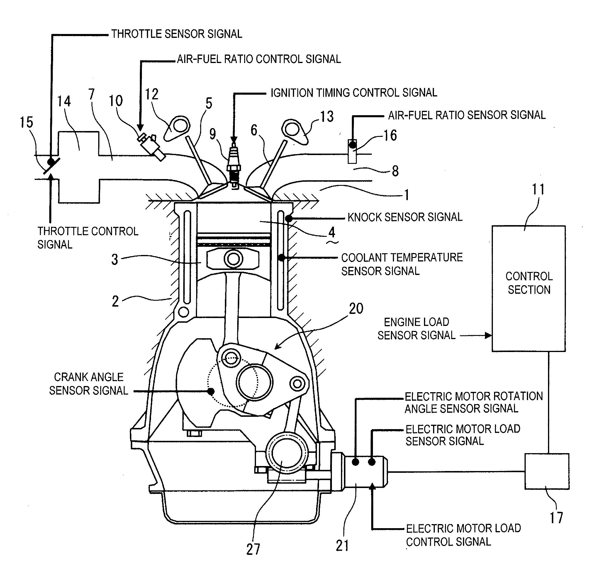
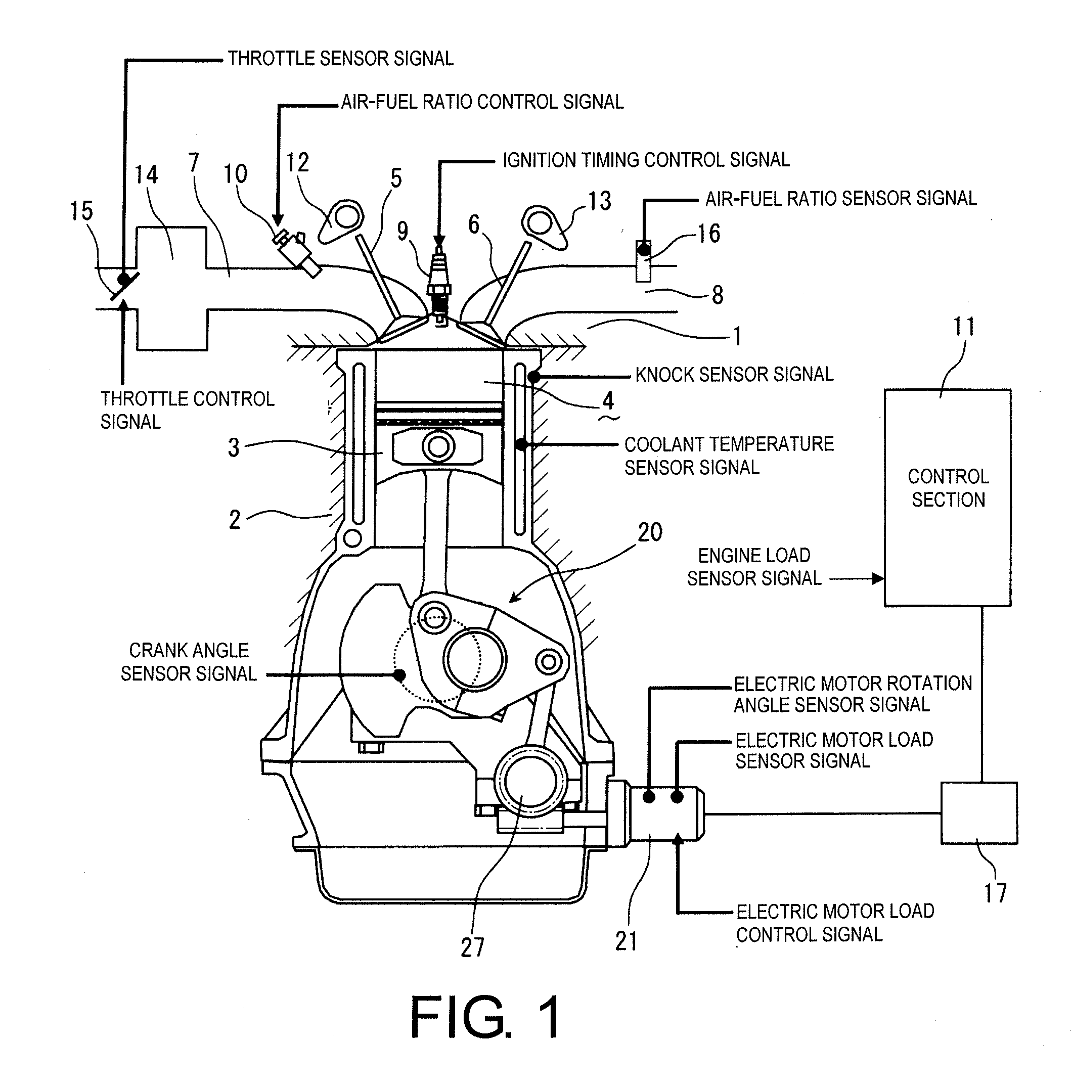
[0025]Referring initially to FIG. 1, a spark ignition type of internal combustion engine is illustrated that is equipped with a variable compression ratio engine control apparatus in accordance with a first embodiment. The internal combustion engine can be other type of gasoline engine as needed and / or desired. As explained below, the variable compression ratio engine control apparatus controls a variable compression ratio engine by setting a low target compression ratio based on an engine rotational speed such that during a deceleration operating state in which a fuel cut is executed, combustion stability is ensured when the engine is restarted a...


PUM


Abstract

A variable compression ratio engine control apparatus includes a fuel injection device, a variable compression ratio device, a target compression ratio setting section and a compression ratio controlling section. The fuel injection device injects fuel into an engine for combustion. The variable compression ratio device varies an engine compression ratio of the engine. The target compression ratio setting section sets a target compression ratio. The compression ratio controlling section controls the engine compression ratio toward the target compression ratio. The target compression ratio setting section sets the target compression ratio based on an engine rotational speed, during a fuel cut operating state in which fuel injection by the fuel injection device is stopped.

Description

CROSS-REFERENCE TO RELATED APPLICATIONS[0001]This application claims priority to Japanese Patent Application No. 2011-090736, filed on Apr. 15, 2011. The entire disclosure of Japanese Patent Application No. 2011-090736 is hereby incorporated herein by reference.BACKGROUND[0002]1. Field of the Invention[0003]The present invention generally relates to an engine control for a variable combustion ratio engine control apparatus or method for varying an engine compression ratio.[0004]2. Background Information[0005]Currently, some conventional engines are provided with a variable compression ratio control that varies the engine compression ratio. For example, a variable compression ratio engine control apparatus is disclosed in Japanese Laid-Open Patent Publication No. 2005-30223 that utilizes a piston-crank mechanism having a plurality of links. With the technology presented in that publication, a fuel cut control is executed to stop fuel injection during a deceleration operating state. A...

Claims


Application Information

Patent Timeline
IPC IPC(8): F02B75/04
CPCF02D15/00F02D15/02F02D2200/101F02D41/123F02D41/065
Inventor KAMADA, SHINOBU
Owner NISSAN MOTOR CO LTD
Why Eureka
Try Eureka