Snap fitting for plumbing

Inactive Publication Date: 2013-03-07
KRIENS JR DAVID J
View PDF9 Cites 13 Cited by
  • Summary
  • Abstract
  • Description
  • Claims
  • Application Information

AI Technical Summary

Benefits of technology

[0016]According to yet another aspect of the present invention, a method includes providing a snap fitting having a main body formed of plastic and shaped to extend partially around a cylindrical pipe to snap over the pipe and a connector for an additional line extending from the main

Problems solved by technology

Whenever a pipe is cut additional problems are introduced.
One example of such a problem is the access area.
If the pipe is under the floor this may involve cutting out a large portion of flooring.
If the pipe is underground this may involve needing to dig out a large area.
Another problem which occurs when a pipe is cut and a portion with a leak is removed and replaced involves aligning the ends of the pipe with the replacement portion.
For example when the pipe is underground the ground may settle differently on opposite sides of the removed portion making it more difficult to obtai

Method used


Image

  • Snap fitting for plumbing
  • Snap fitting for plumbing
  • Snap fitting for plumbing

Examples


Example

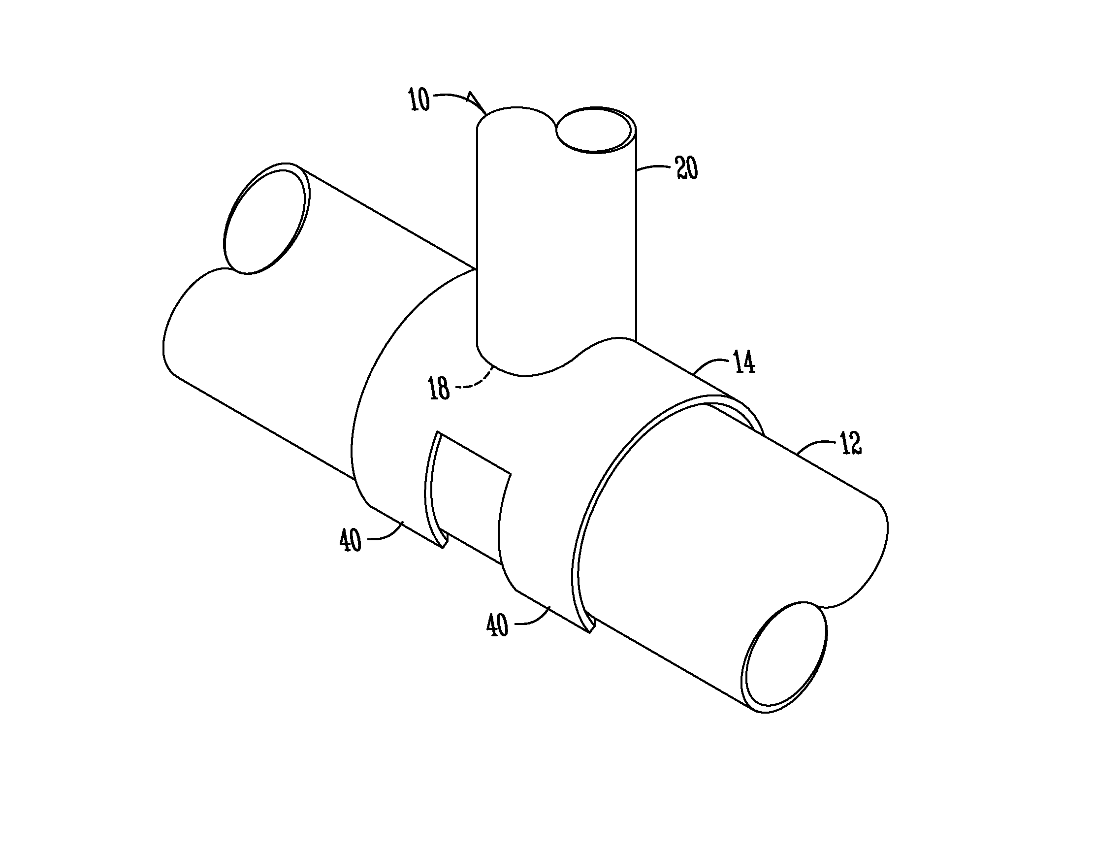
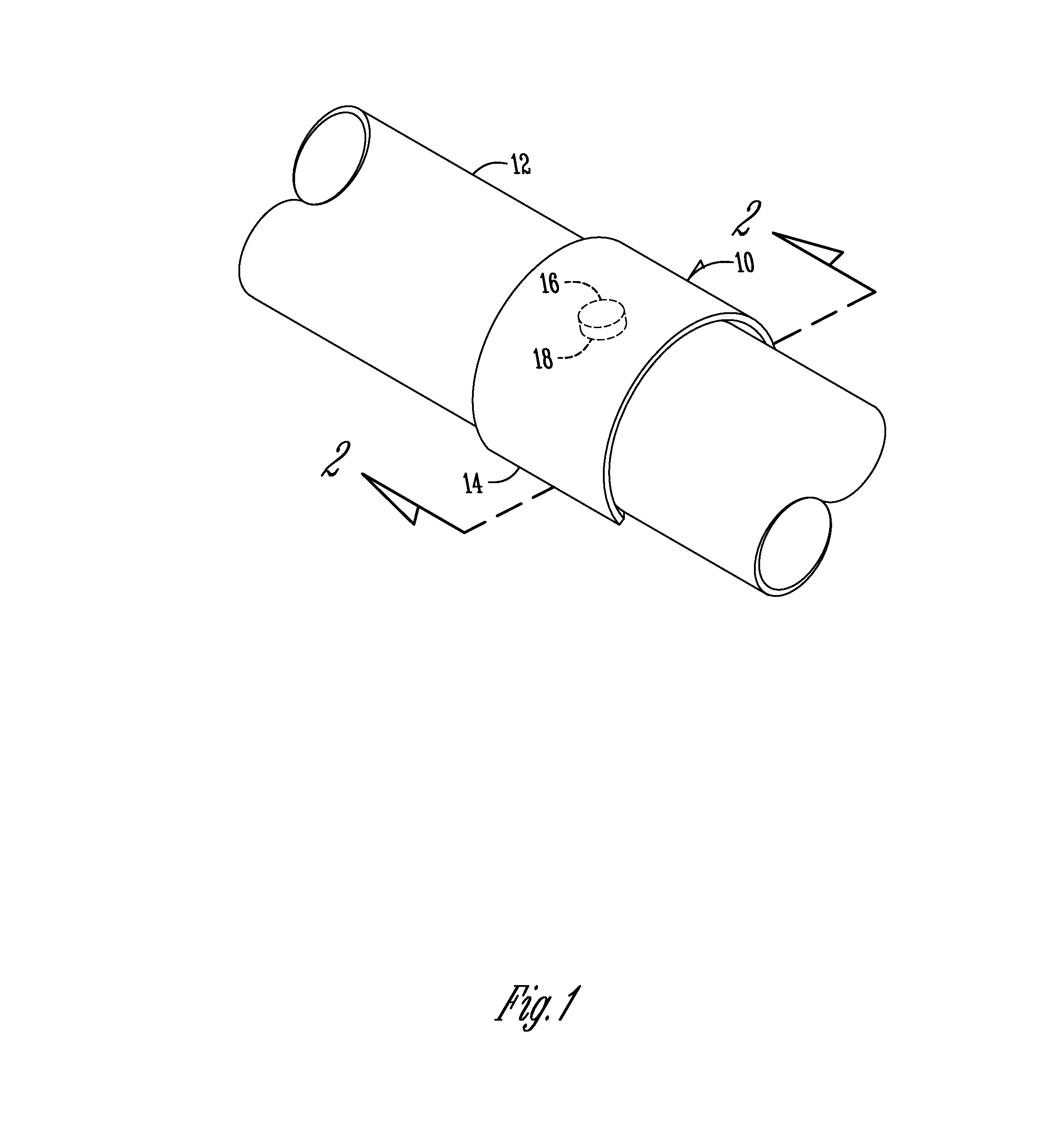
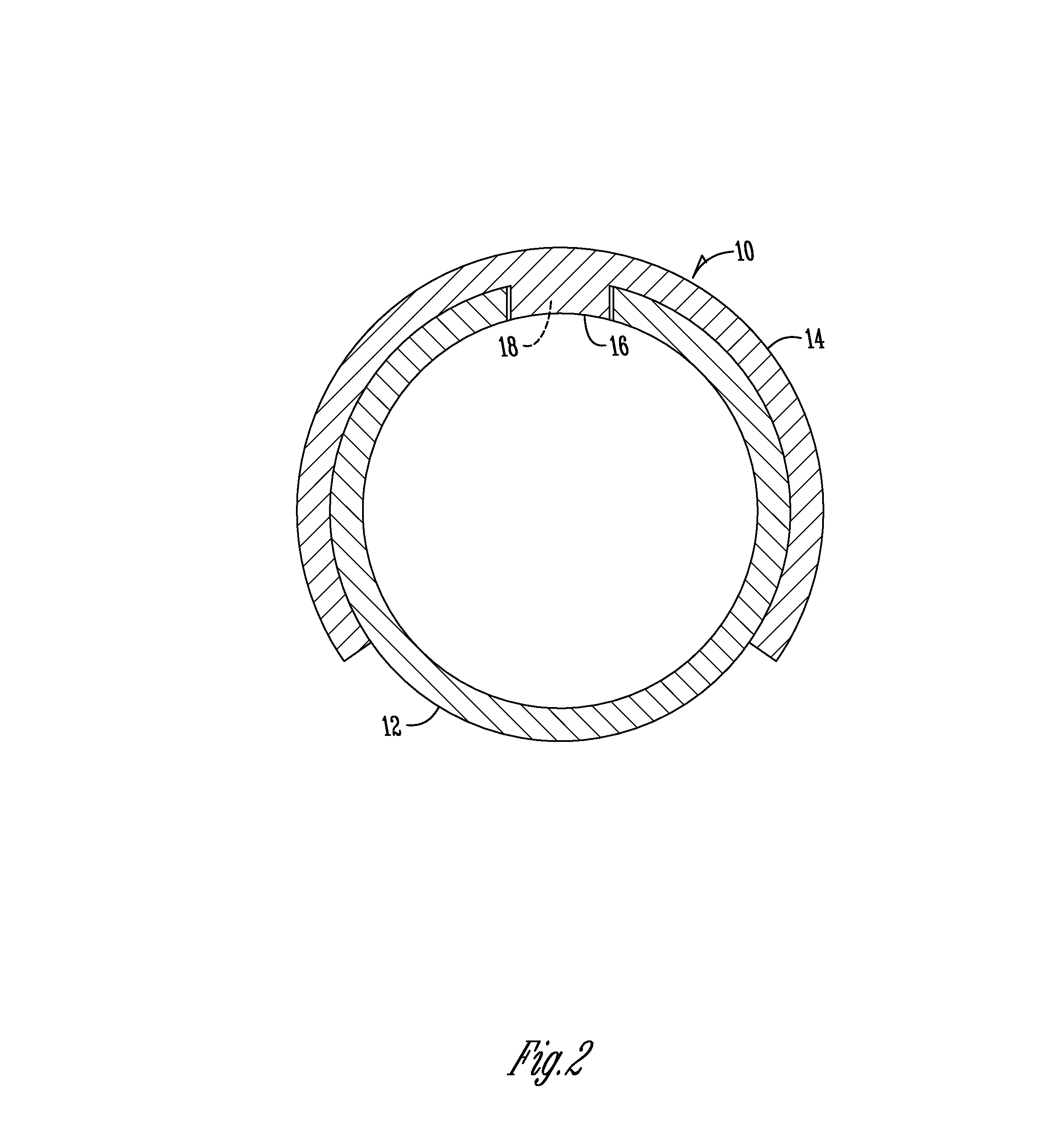
[0025]FIG. 1 illustrates a snap fitting 10 positioned on a pipe 12. The snap fitting 10 has a main body 14 which extends generally annularly around a portion of the pipe 12. The main body 14 preferably extends over 50 percent around the pipe 12 which allows the snap fitting 10 to snap fit in place. Although not shown, solvents and glues may coated on the interior of the main body 14 and the exterior of the pipe 12 to attach the fitting 10 to the pipe 12.

[0026]There is an inset 16 which may be an integral portion of the snap fitting 10 or may be a separate piece which is attached to the snap fitting 10 (such as through a solvent cement or otherwise). The inset 16 fits within a hole 18 in the pipe 12 to plug the hole 18.

[0027]The snap fitting 10 may be made out of any number of plastic materials. One such type of material which is used in plumbing is polyvinylchloride, although other types of plastic materials may be used. The snap fitting may have a wall thickness substantially the s...


PUM

PropertyMeasurementUnit
Fractionaaaaaaaaaa
Circumferenceaaaaaaaaaa

Abstract

A snap fitting for use in plumbing is provided. The snap fitting includes a main body formed of plastic and shaped to extend partially around a cylindrical pipe to snap over the pipe and an inset for extending from an interior side of the main body into a hole in the cylindrical pipe.

Description

CROSS-REFERENCE TO RELATED APPLICATIONS[0001]This application claims priority under 35 U.S.C. §119 to provisional application Ser. No. 61 / 530,446 filed Sep. 2, 2011, herein incorporated by reference in its entirety.FIELD OF THE INVENTION[0002]The present invention relates to plumbing. More particularly, the present invention relates to snap fittings which may be used in various plumbing applications including in pipe repairs and in providing wye or T fittings.BACKGROUND OF THE INVENTION[0003]Often times in plumbing, pipes must be cut as part of the process of repairing a leak or adding another line (such as a T or wye connection). Whenever a pipe is cut additional problems are introduced.[0004]One example of such a problem is the access area. When a pipe is cut as a part of repair, there needs to be sufficient access to the area to perform the necessary repair. If the pipe is in the wall this may involve cutting out a large area of drywall. If the pipe is under the floor this may in...

Claims


Application Information

Patent Timeline
IPC IPC(8): F16L55/168F16L41/00
CPCF16L41/004F16L41/12F16L55/17F16L47/30F16L47/26F16L55/168F16L55/18B29C65/4895B29C66/5221B29C66/5224B29C66/52241B29K2027/06B29L2023/22
Inventor KRIENS, JR., DAVID J.
Owner KRIENS JR DAVID J
Why Eureka
Try Eureka