
Tee and Unload Line with Integrated Cam Lock

Active Publication Date: 2014-03-27
BULK TANK
View PDF19 Cites 5 Cited by
  • Summary
  • Abstract
  • Description
  • Claims
  • Application Information

AI Technical Summary

Benefits of technology

The present invention is a device that allows for unloading of granular materials from a flow line. The device includes a tee with a grooved lock coupler integrated upon its surface. The coupler is easily connected to the flow line and securely locked into the tee to prevent any contamination of the mineral material. The device is easy to install and has a smooth transition during continued usage. Additionally, the tee has grooves that enhance the retention of the coupler, increasing its useful life for repetitive applications. Overall, the invention ensures safe and efficient unloading of granular materials from flow lines.

Problems solved by technology

The transition from the tee to within the flow line usually provided a change to a different diameter, which could disrupt the routine of flow of the granular material under air pressure, and cause such turbulence to effect a reduction in the speed and efficiency of the unloading process.
This further caused a pressure drop during usage of such prior art devices which also reduced the speed and efficiency of the unloading process.
Furthermore, the use of the locking cams, within their grooves, would result in excessive wear to the entire tee, and which would necessitate a replacement of the tee, on a more frequent basis, than desired.
Furthermore, the usual form of interconnection of the cam locking device, of the older prior art styles, would necessitate a threaded connection of its coupling with the flow line, and which would create that inequality in the internal diameters between the cam lock coupling, and the hose and pipe to which it connected, which caused the type of disruption in flow, as previously reviewed, which would lead to inefficiencies in discharge of the dry bulk material, and an undesired pressure drop, during usage.
Another prior art type of means for connection of the flow line and its pipe to the tee included that threaded fitting, that would screw onto the approximate end of the tee, and the problem with this type of connection is that usually some of the threads formed internally of a coupler would be exposed to the passing granular material, and hence, once again, caused disruption of flow, turbulence in the movement of the dry bulk material, which would lessen, once again, the efficiency of conveyance of the bulk material from the tank trailer, etc., to a distant location for either unloading, storage, or for further processing.
Furthermore, having exposed threads within the flow line, from the threaded coupler, also furnished an abrasive location, where disruption of the flow of the granular material would occur, thereby acting as an excessive friction and wear point, leading towards a wear out of the tee, and its coupler, at that location, requiring their total replacement.
The problem with that type of coupling was that there was normally a gap formed between these two components, and the gap between the fitting and the flow line or pipe was a source for contamination, and wear, as aforesaid, that would accelerate the fatigue of the components, at that location, as a result thereof.

Method used


Image

  • Tee and Unload Line with Integrated Cam Lock
  • Tee and Unload Line with Integrated Cam Lock
  • Tee and Unload Line with Integrated Cam Lock

Examples


Embodiment Construction

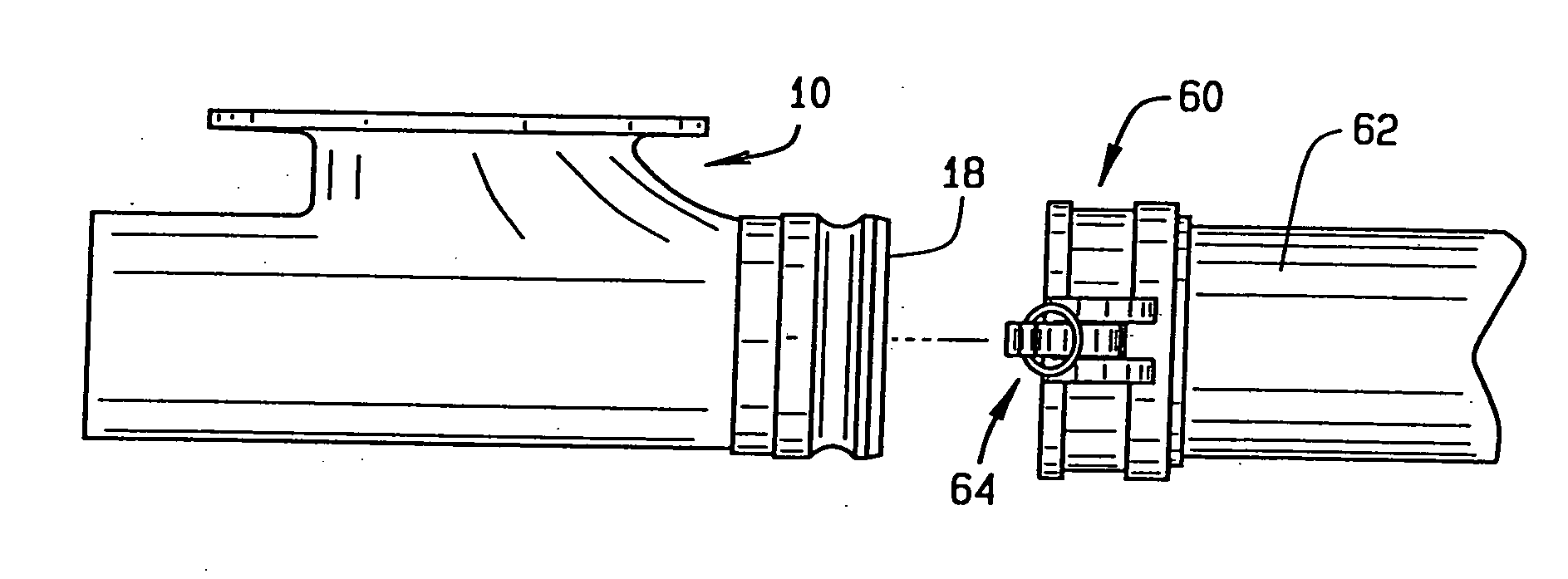
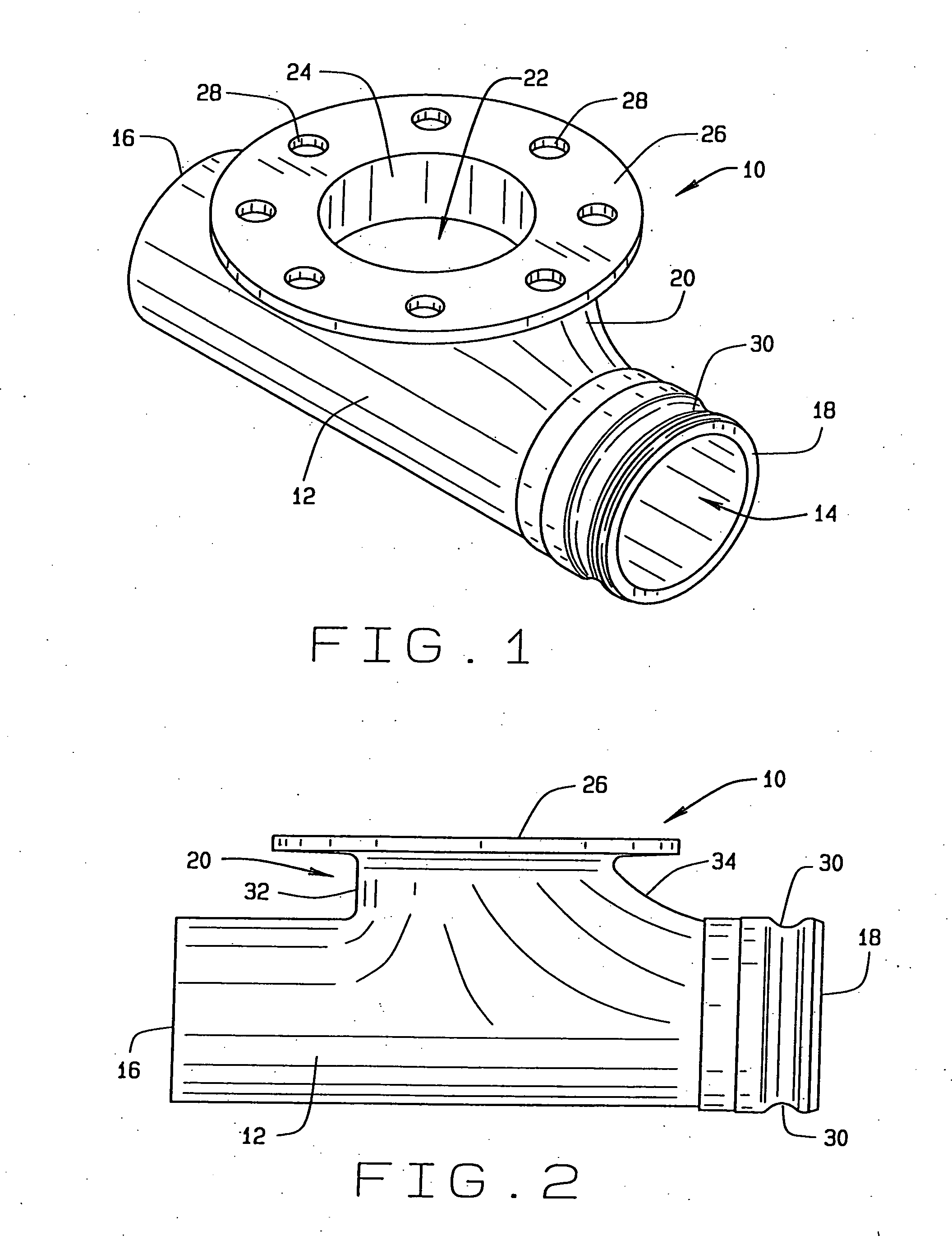
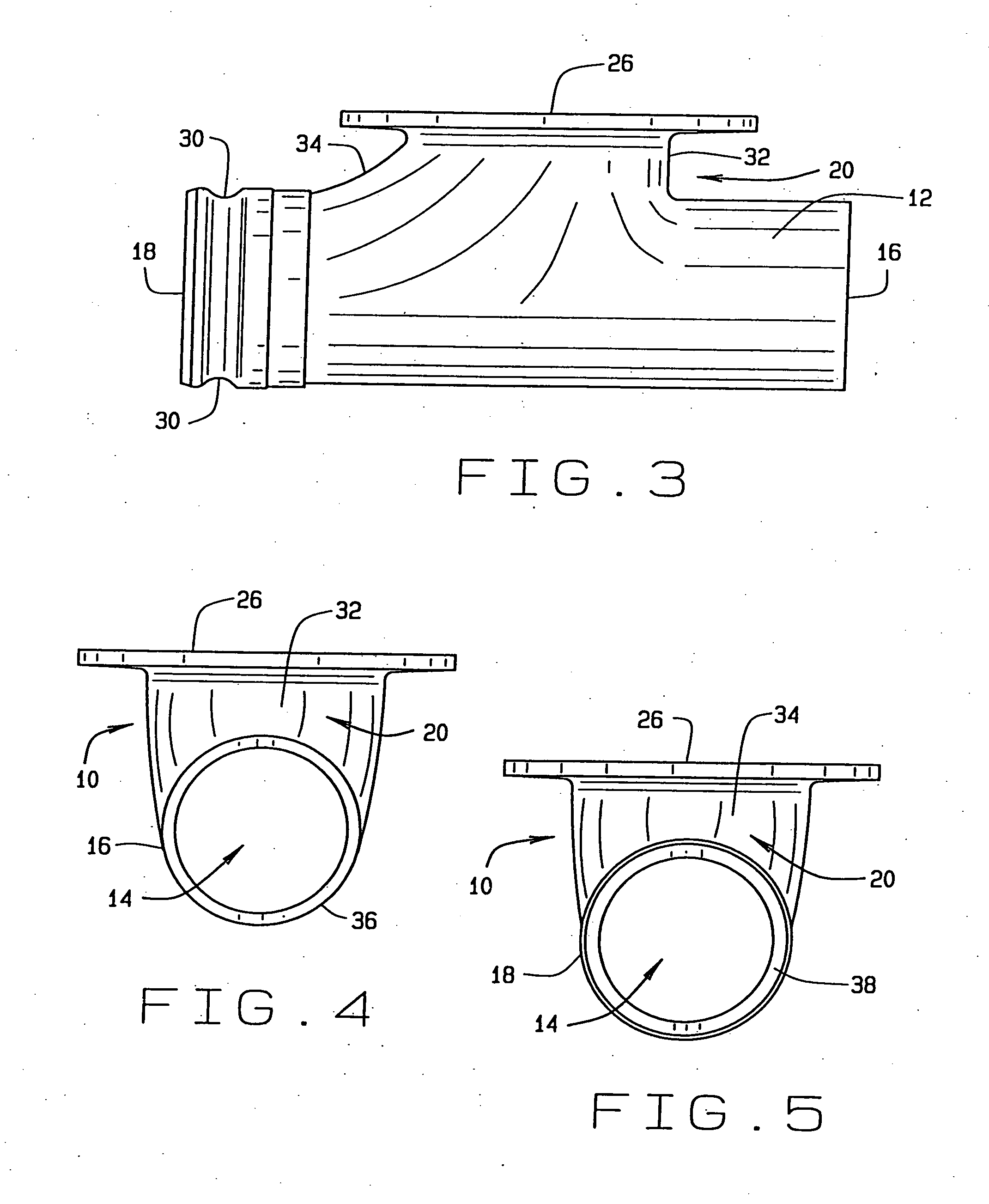
[0036]Referring now to the drawings, wherein like numbers refer to like items, number 10 identifies a preferred embodiment of a tee constructed according to the present disclosure. With reference now to FIG. 1, the tee 10 comprises a longitudinal flow body or section 12 having an interior longitudinal channel 14 that extends from a first end 16 to a second end 18. The tee 10 has an upstanding portion 20 leading towards an inlet end 22 that has a vertical channel 24. An integral flange 26 is provided at the inlet end 22 having a number of bolt holes 28. The second end 18 is formed having an exterior annular groove 30. The first end 16 is adapted to being connected to a source of pressurized air. The inlet end 22 is adapted to being connected to an underside of a tank trailer, railroad car, hopper, or other storage device that has contained therein granular material or dry bulk material such as grain or corn. Bolts (not shown) may be used to bolt the tee 10 through the bolt holes 28 p...


PUM


Abstract

A grooved lock coupler for holding a tee to a flow line for forced air conveyance and unloading of dry bulk granular material from a storage container vehicle is disclosed which comprises a tee having a first end, a second end, an inlet end, and a circumferential groove provided on the first end and a coupler for interconnecting to a flow line from the tee, the coupler having a cam lock fastener pivotally mounted on the coupler, the cam lock fastener cooperating with an opening in the coupler proximate the fastener to allow for the cam lock to extend through the opening in the coupler and to engage within the groove to lock the flow line and coupler to the tee in preparation for an unloading process.

Description

CROSS REFERENCE TO RELATED APPLICATION[0001]This application claims priority to the provisional patent application having Ser. No. 61 / 744,389, filed on Sep. 26, 2012, design patent application having Serial No. 29 / 421,194, filed on Jun. 12, 2012, which claimed priority to the non-provisional patent application Ser. No. 13 / 200,625, filed on Sep. 27, 2011, which claimed priority to the non-provisional patent application Ser. No. 12 / 249,672, filed on Oct. 10, 2008, now U.S. Pat. No. 8,091,925, which claimed priority to the provisional patent application Ser. No. 61 / 030,777, filed on Feb. 22, 2008, which is related to U.S. Pat. No. 6,786,362, which also claimed priority to the continuation-in-part design patent application having Serial No. 29 / 395,947, filed on Apr. 26, 2012, which claimed priority to the design patent application having Serial No. 29 / 362,245, filed on May 21, 2010, and also claimed priority to the provisional patent application Ser. No. 61 / 688,864, filed on May 23, 201...

Claims


Application Information

Patent Timeline
IPC IPC(8): F16L37/18
CPCF16L37/18F16L41/021
Inventor SISK, DAVID E.
Owner BULK TANK
Learn More