Travel drive device for dump truck

a technology for dump trucks and travel drives, which is applied in the direction of fluid actuated brakes, braking systems, transportation and packaging, etc., can solve the problems of increasing the heat generated amount of wet brakes to exceed the capability of cooling liquid, components of wet brakes are the metallic seal ring in the floating seal is possibly broken or damaged, so as to improve the foreign object trapping function

Active Publication Date: 2013-03-07
NIHON KENKI CO LTD
View PDF6 Cites 18 Cited by
  • Summary
  • Abstract
  • Description
  • Claims
  • Application Information

AI Technical Summary

Benefits of technology

[0017]According to the above arrangement, the foreign-object trapping portion may be configured as the radial gap which provides a radial space between the hub-side O-ring receiving portion provided in the brake hub and the cylindrical projecting portion in the retainer. Therefore, the foreign-object trapping portion is configured such that the radial gap is radially curved in an L-letter shape to the axial gap of the floating seal. Accordingly, even in a case where the foreign object passes through the axial gap between the brake hub and the retainer, the foreign object can be trapped by the foreign-object trap...

Problems solved by technology

However, for example, when a braking operation of applying a braking force by operating the wet brake or releasing the braking force is repeatedly performed in the middle of traveling on a long down-slope, a heat generated amount of the wet brake increases to exceed a capability of the cooling liquid, possibly causing overheating.
In the worst case, components of the wet brake are possibly broken or damaged.
Further, a metallic seal ring in the floating seal is possibly broken or damaged due to generation of seizing, wear or the like on a sliding surface thereof under such a high-temperature condition.
An O-ring of the floating seal is also possibly broken ...

Method used


Image

  • Travel drive device for dump truck
  • Travel drive device for dump truck
  • Travel drive device for dump truck

Examples


first embodiment

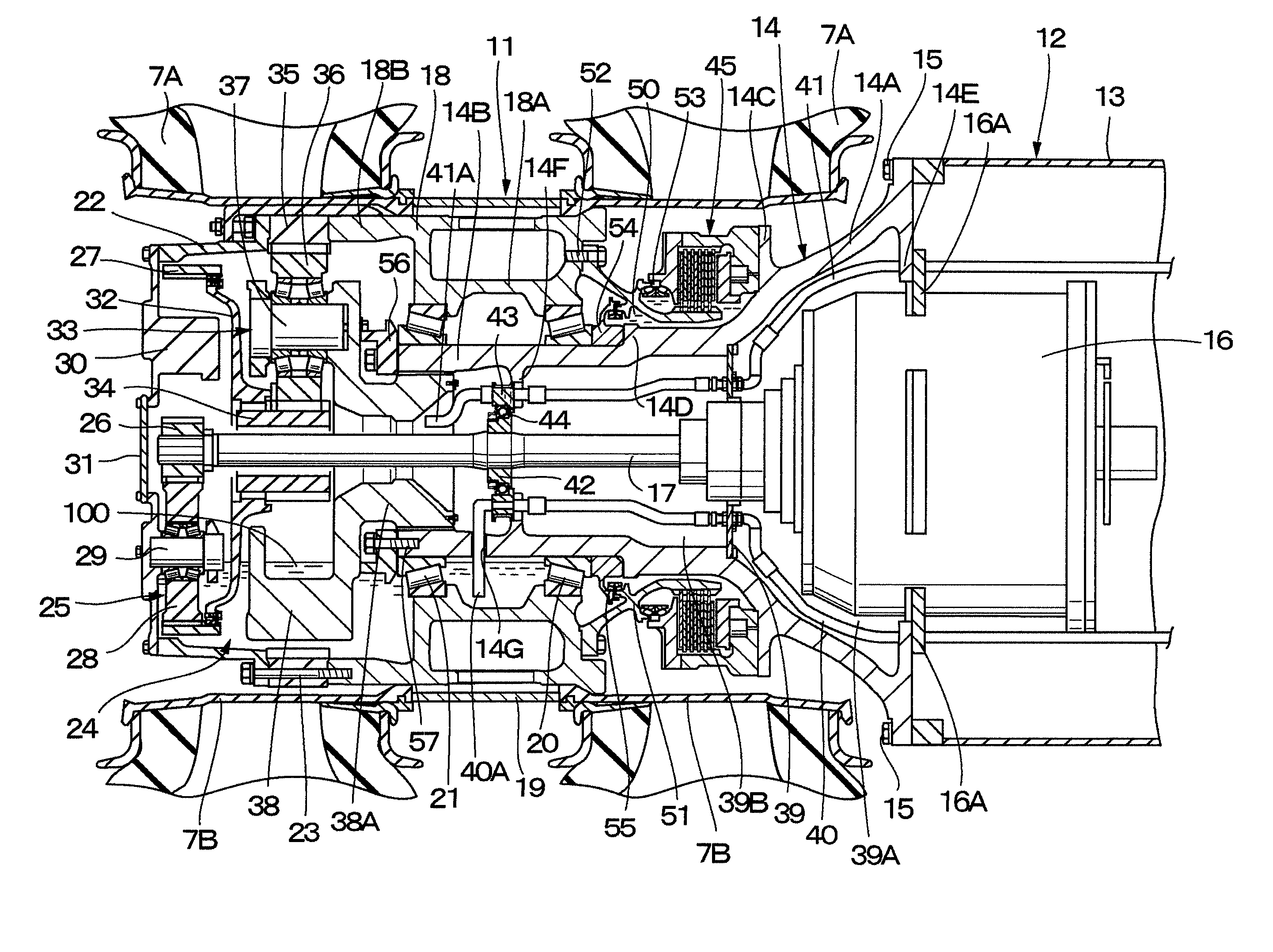
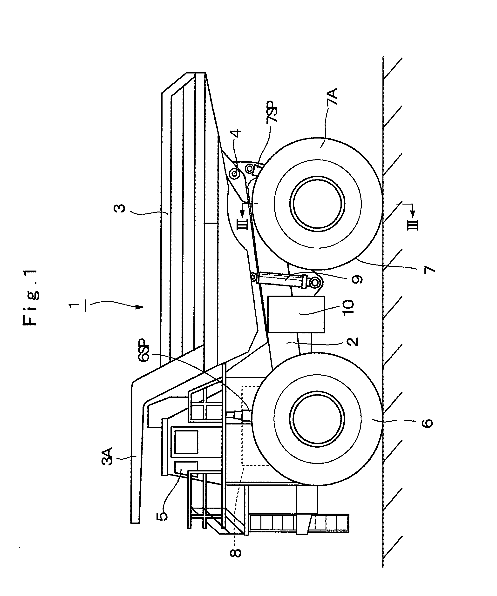
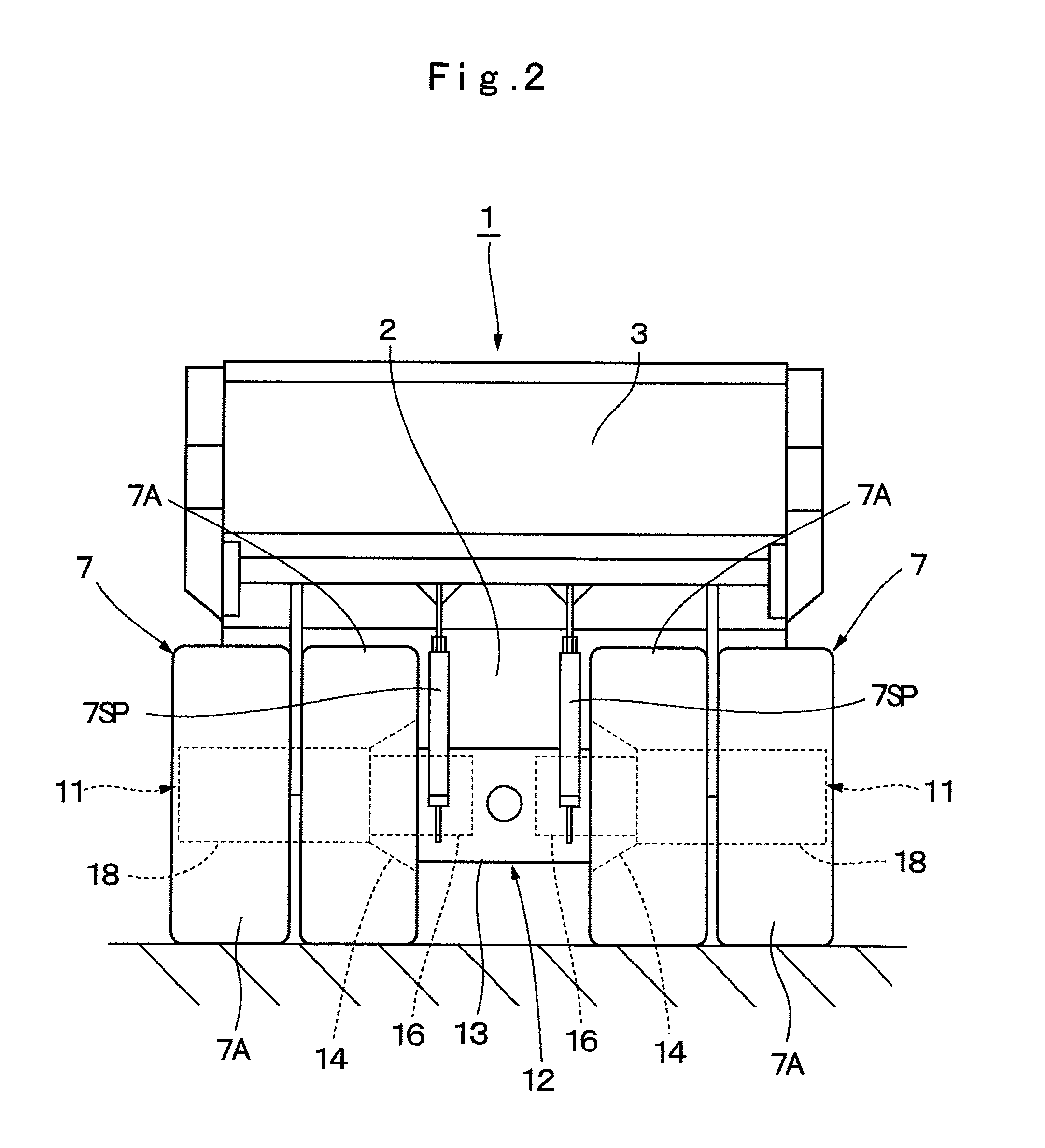
[0026]FIG. 1 to FIG. 5 show a travel drive device for a dump truck according to the present invention.

[0027]In the figure, designated at 1 is a dump truck adopted in the first embodiment. As shown in FIG. 1, the dump truck 1 is constituted by including a vehicle body 2 having a strong frame structure and a vessel 3 as a loading platform liftably mounted on the vehicle body 2.

[0028]The vessel 3 is formed as a large-sized container of an entire length of 10 to 13 meters for loading a large volume of heavy baggage such as crushed stones. A rear-side bottom portion of the vessel 3 is liftably (tiltably) connected to a rear end side of the vehicle body 2 through a connecting pin 4. A protector 3A is integrally provided in a front-side top portion of the vessel 3 in such a manner as to cover a cab 5 to be described later from the upper side.

[0029]The cab 5 is provided in the front portion of the vehicle body 2 to be positioned under the protector 3A. The cab 5 forms an operator's room whi...


PUM


Abstract

A wheel mounting cylinder (18) is rotatably provided on an outer peripheral side of an axle housing (12) through wheel support bearings (20, 21). A wet brake (45) is provided between the axle housing (12) and the wheel mounting cylinder (18) for applying a braking force to rotation of the wheel mounting cylinder (18). A seal mechanism (55) is provided between the wet brake (45) and the wheel support bearing (20) for keeping a cooling liquid (50) of the wet brake (45) in a sealed state to lubricant oil (100) in the wheel mounting cylinder (18). A foreign-object trapping portion (58, 62) is provided between the wheel support bearing (20) and the seal mechanism (55) for trapping foreign objects flowing from the seal mechanism (55) toward the wheel support bearing (20).

Description

TECHNICAL FIELD[0001]The present invention relates to a travel drive device for a dump truck which is suitably used in transporting crushed stones excavated from such as an open-pit stope, a stone quarry, a mine or the like.BACKGROUND ART[0002]In general, a large-sized transporter vehicle called a dump truck has a liftable vessel (loading platform) on a frame of a vehicle body, and transports crushed stones or the like in a state of a heavy baggage being loaded in a large quantity on the vessel.[0003]Therefore, each travel drive device for driving drive wheels of the dump truck for traveling is provided with a cylindrical axle housing mounted in a non-rotating state on a vehicle body, a rotational shaft provided to axially extend in the axle housing and driven by a drive source such as an electric motor for rotation, a wheel mounting cylinder which is rotatably mounted on an end-side periphery of the axle housing through bearings and to which vehicle wheels are mounted, and a reduct...

Claims


Application Information

Patent Timeline
IPC IPC(8): B60K17/14
CPCB60K17/046F16D55/40F16D2121/04F16D65/853B60T1/062F16D65/0031
Inventor SHIBUKAWA, TAKESHIINOUE, NAOYUKITANAKA, KYOKOHAGIHARA, SHINICHIROSHINOHARA, TAKESHI
Owner NIHON KENKI CO LTD
Why Eureka
Try Eureka