Device and method for controlling charge of assembled battery

US20130057218A1Inactive Publication Date: 2013-03-07OMRON AUTOMOTIVE ELECTRONICS CO LTD

Image

  • Device and method for controlling charge of assembled battery
  • Device and method for controlling charge of assembled battery
  • Device and method for controlling charge of assembled battery

Examples


Embodiment Construction

[0026]Hereinafter embodiments of the present invention will be described with reference to the drawings. The case that the invention is applied to an assembled battery mounted on an electric automobile is cited by way of example.

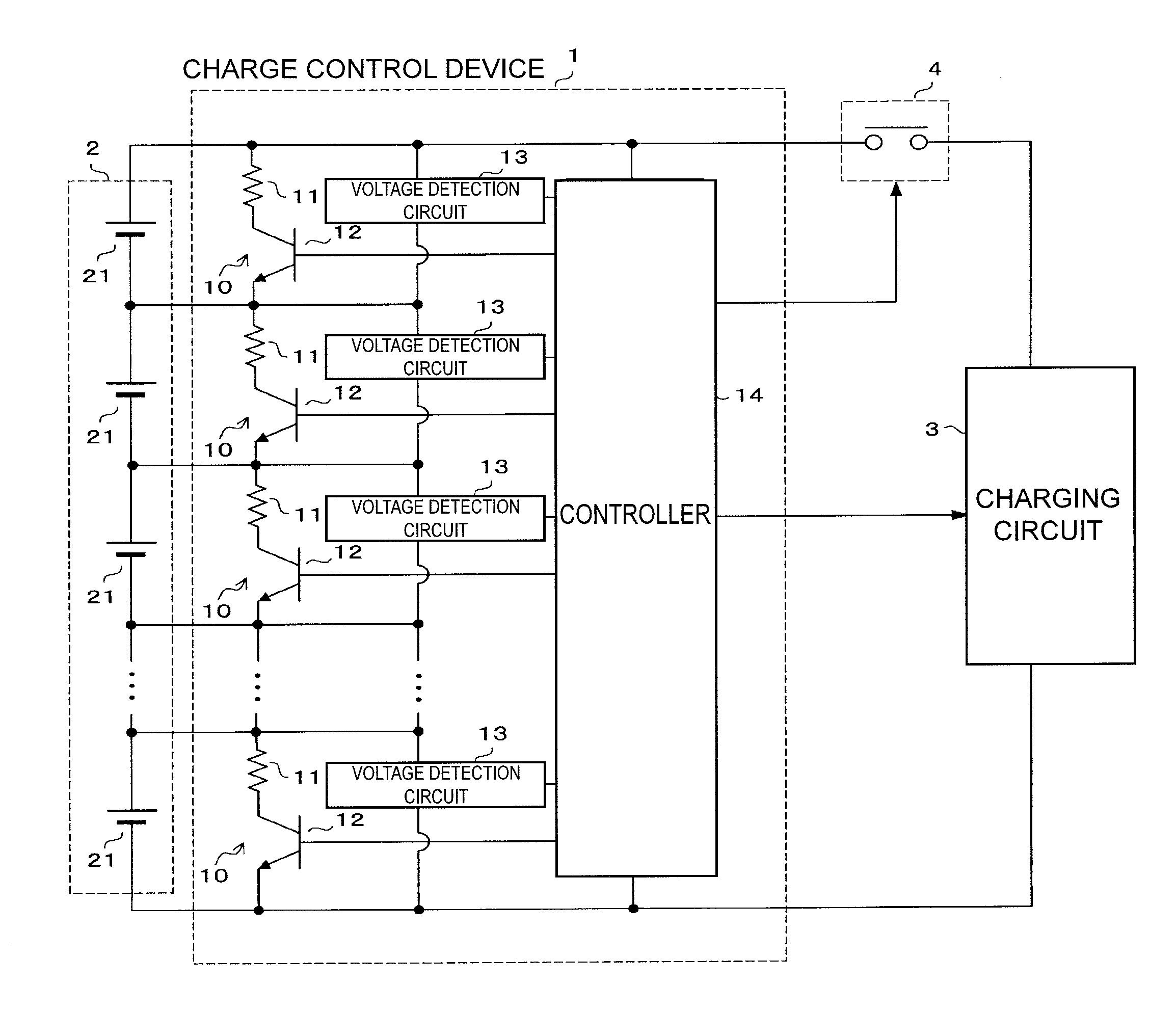
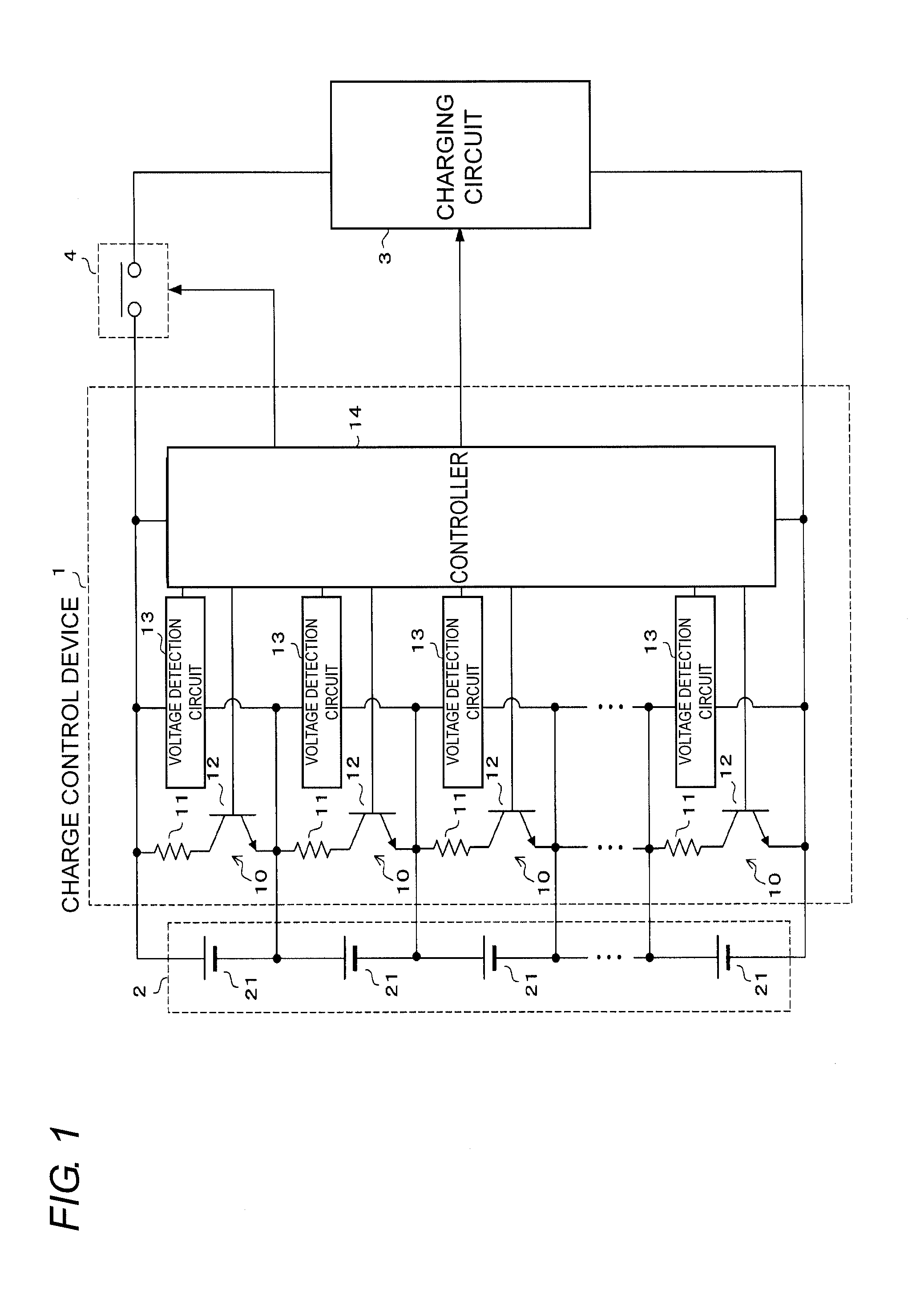
[0027]A configuration of a charge control device of the embodiment will be described with reference to FIG. 1. Referring to FIG. 1, a charge control device 1 is provided between an assembled battery 2 and a charging circuit 3 to control charge of the assembled battery 2. The assembled battery 2 includes a plurality of batteries 21 connected in series. For example, each battery 21 is a secondary battery, such as a lithium-ion battery. A contactor 4 is provided between the charge control device 1 and the charging circuit 3.

[0028]In the charge control device 1, each battery 21 of the assembled battery 2 includes a discharge circuit 10 that is constructed by a series circuit of a resistor 11 and a transistor 12 and a voltage detection circuit 13 that detects a v...


PUM


Abstract

An assembled-battery charge control device controls charge of an assembled battery including a plurality of secondary batteries connected in series. The assembled-battery charge control device includes a discharge circuit that includes a series circuit of a resistor and a switching element, the series circuit being connected in parallel with each battery of the assembled battery, and the discharge circuit allowing the battery corresponding to the switching element to discharge by turning on the switching element. The assembled-battery charge control device also includes voltage detection unit that detects a voltage at each battery of the assembled battery and a control unit that determines the battery that needs suppression of the charge based on the voltage at each battery detected by the voltage detection unit, and turns on the switching element corresponding to the battery.

Description

BACKGROUND OF THE INVENTION[0001]1. Technical Field[0002]The present invention relates to a charge control technology of reducing a variation in voltage among batteries constituting an assembled battery.[0003]2. Related Art[0004]For example, an electric automobile is provided with a high-voltage battery serving as a power supply for a drive motor and a in-vehicle device. Generally the high-voltage battery is constructed by so-called an assembled battery in which a plurality of secondary batteries, such as lithium-ion batteries, are connected in series. In the assembled battery, dischargeable electric energy (hereinafter referred to as a “discharge capacity”) varies among the batteries due to a variation in battery characteristic of each battery. For the secondary battery, since a battery life is shortened by overcharge or over discharge, once one of the batteries constituting the assembled battery comes into a charge completed state or in a discharge completed state, it is necessary...

Claims


Application Information

Patent Timeline
07 Mar 2013
Publication
US20130057218A1
IPC
H02J7/00; H02J7/02
CPC
G01R31/362; G01R31/3658; H01M10/441; H01M10/46; H01M10/482; Y02T10/7055; H02J7/0016; H02J7/0021
Inventors
SAWAYANAGI, TOMOHIRO; KITAHARA, NAOKI