
Method and apparatus for controlling a converter

a technology of converters and control devices, applied in the direction of control systems, electric generator control, dynamo-electric converter control, etc., can solve the problems of sudden drop in the voltage of the grid, electrical disturbance, voltage gaps, etc., and achieve the effect of reducing maintenance work and increasing the reliability of the system

Inactive Publication Date: 2013-03-07
INGETEAM POWER TECH
View PDF12 Cites 15 Cited by
  • Summary
  • Abstract
  • Description
  • Claims
  • Application Information

AI Technical Summary

Benefits of technology

This invention relates to a way of controlling a converter used in machines that have shunt protection circuits installed between the motor and the converter. The control procedure reduces overvoltages that can occur when the shunt protection circuit is disconnected or interrupted, which can protect the converter from motor-generated electrical disturbances. This approach may reduce the need for specific circuits to reduce overvoltages and make it more efficient. It also optimizes the operation of the converter elements, increases reliability, and reduces maintenance work.

Problems solved by technology

Voltage gaps are sudden drops in the voltage of the grid to which the generators and converters are connected.
These disruptions cause situations of abnormal operation in which there are severe electrical disturbances that must be detected by the control units of the converters in order to take the measures necessary to guarantee functional continuity and operation within the safe functional range of the components that make up the converters.

Method used


Image

  • Method and apparatus for controlling a converter
  • Method and apparatus for controlling a converter
  • Method and apparatus for controlling a converter

Examples


Embodiment Construction

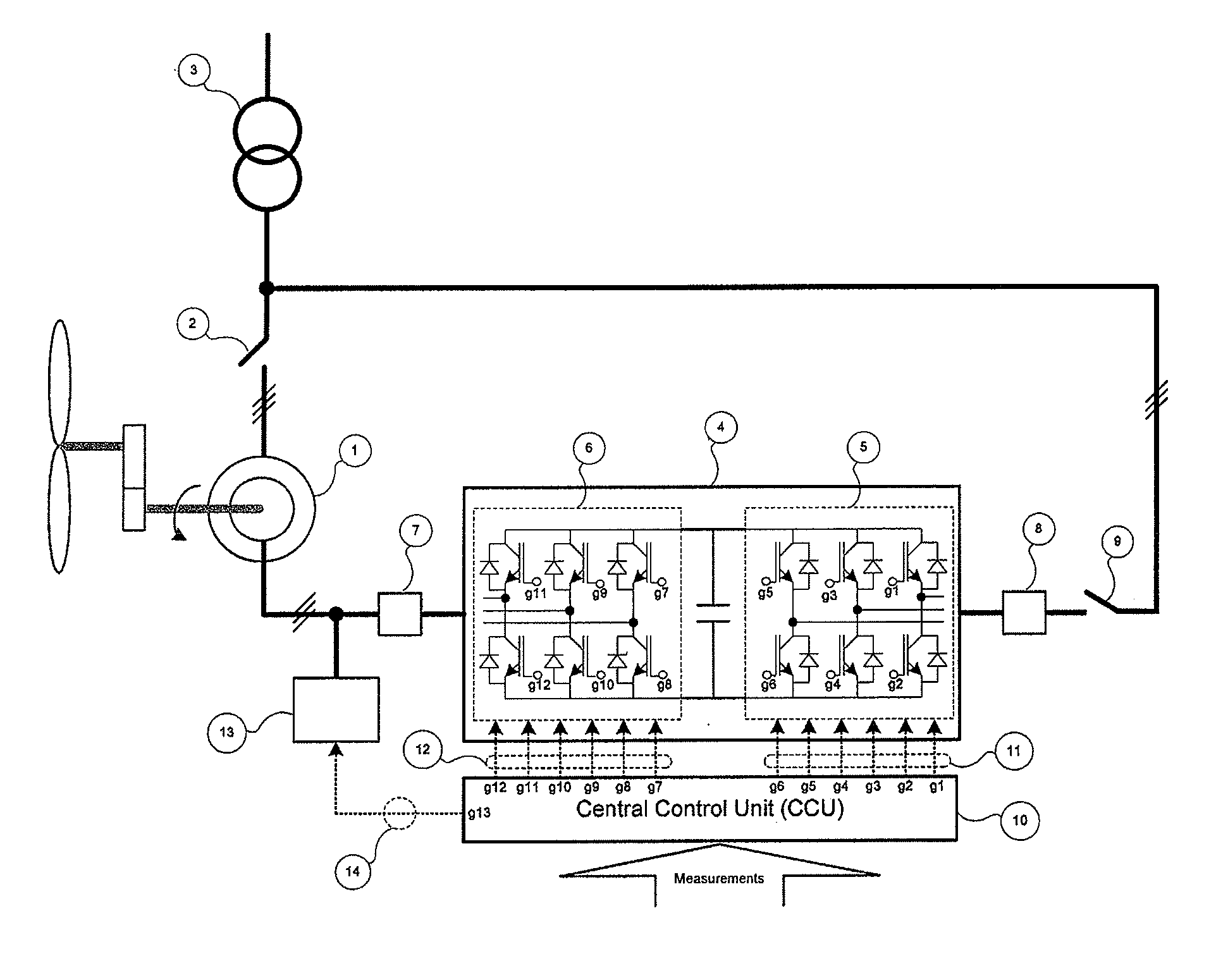
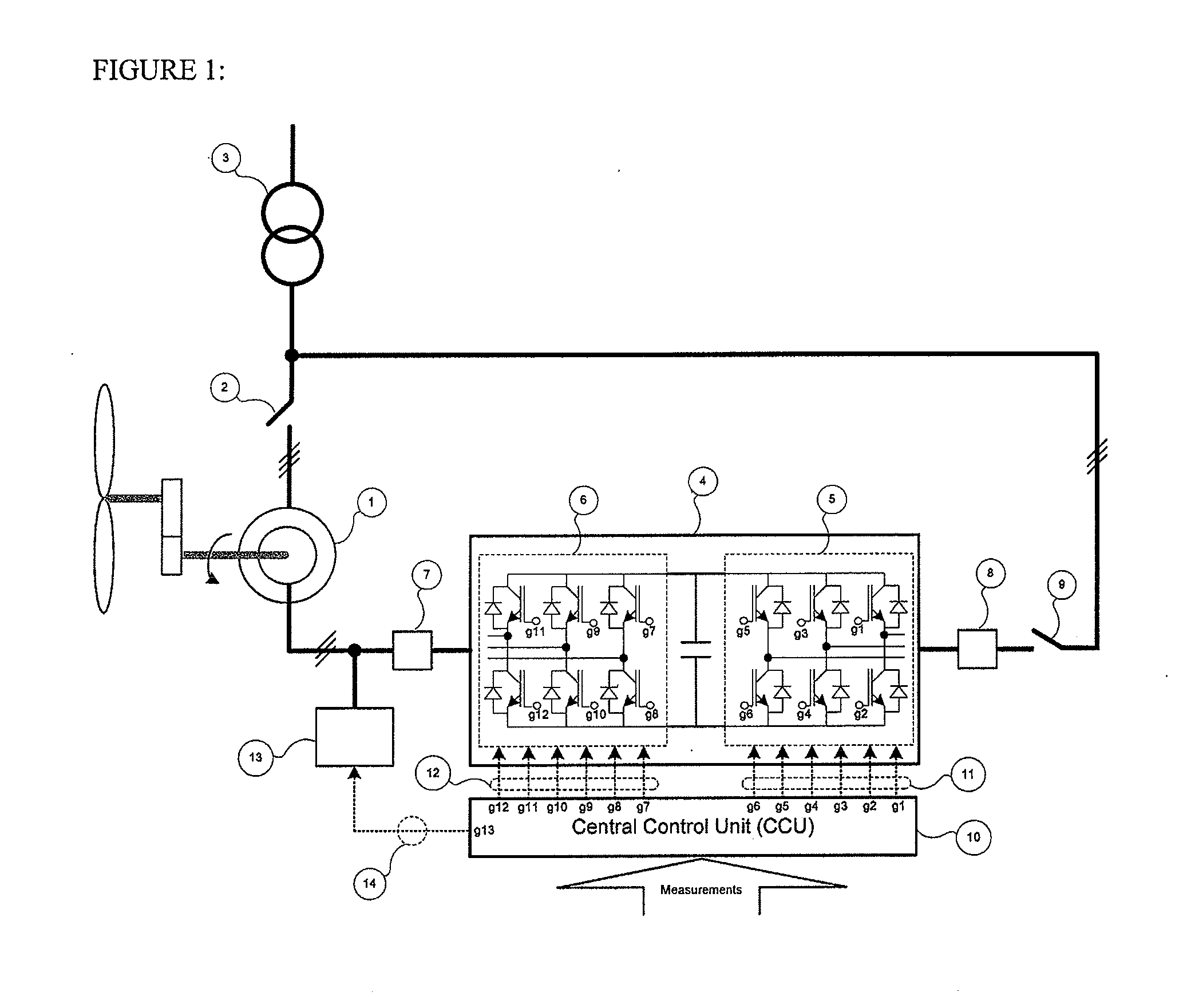
[0031]FIG. 1 shows a single-wire diagram of a wind power generation application based on a doubly-fed topology. The diagram shows the different parts that make up the application including the header transformer that will adapt the power supply, the wound rotor asynchronous generator, the frequency converter made up of the inverter and the rectifier, the shunt protection circuit, the grid connection filter, the generator connection filter, the main control unit, the generator-grid connection contact and the rectifier-grid connection contact.

[0032]As shown in FIG. 1, the doubly-fed asynchronous generator 1 includes a stator connected to the electricity grid through the stator coupling contact 2. The transformer 3 adapts the voltage levels of the electricity grid to which the generator 1 and frequency converter 4 are connected. The frequency converter 4 includes a grid side converter or rectifier 5 and a machine side converter or inverter 6. Also shown is a connection filter 7 dispose...


PUM


Abstract

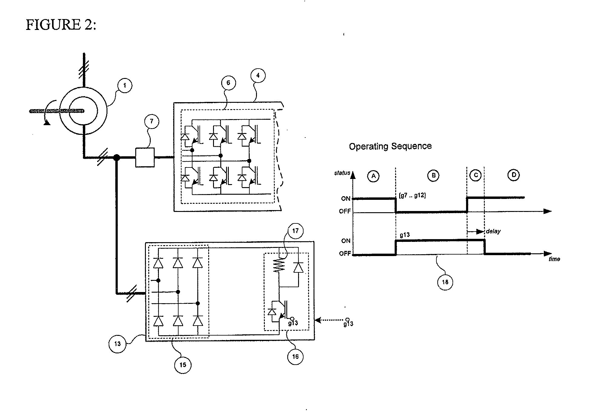
An apparatus and method of controlling an electrical generating apparatus is provided. The apparatus includes an electrical generator configured to be connected to an electrical grid and a converter comprising an inverter connected to a rotor of the electrical generator. The apparatus also includes a shunt protection circuit connected to the inverter and the rotor of the electrical generator and a control unit configured to activate and deactivate the inverter and the shunt protection circuit. The control unit is configured to, in response to determining that an abnormal condition is occurring in the electrical generator or an electrical grid to which the electrical generator is connected, deactivate the inverter and activate the shunt protection circuit. Also, after it is determined that the abnormal condition has passed, the control unit is configured to activate the inverter before deactivating the shunt protection circuit.

Description

CROSS-REFERENCE TO RELATED PATENT APPLICATION[0001]This application claims the benefit of U.S. Provisional Patent Application No. 61 / 530,203 filed on Sep. 1, 2011 in the U.S. Patent Trademark Office, the disclosure of which is incorporated herein in its entirety by reference.BACKGROUND OF THE INVENTION[0002]1. Field of the Invention[0003]Apparatuses and methods consistent with the present invention relate to a converter utilized in a wind turbine generator.[0004]2. Description of the Related Art[0005]The use of frequency converters in energy conversion systems is ever more common due to the advantages they bring when controlling electrical machines. Notably, they are used to convert mechanical energy into electrical energy in generators or to convert electrical energy into mechanical energy in motors. The main advantages of using converters are the improvement in energy efficiency and the ability to control the energy flow more accurately and dynamically.[0006]Wind power generation ...

Claims


Application Information

Patent Timeline
IPC IPC(8): H02P9/48H02H7/06
CPCH02H7/06H02P9/007H02P9/48
Inventor AURTENETXEA, SERGIOOLEA, ENEKOGARMENDIA, IKERCARCAR, AINHOA
Owner INGETEAM POWER TECH
Learn More