

Substrate with built-in component
- Summary
- Abstract
- Description
- Claims
- Application Information
AI Technical Summary
Benefits of technology
Problems solved by technology
Method used
Image

Examples
first preferred embodiment
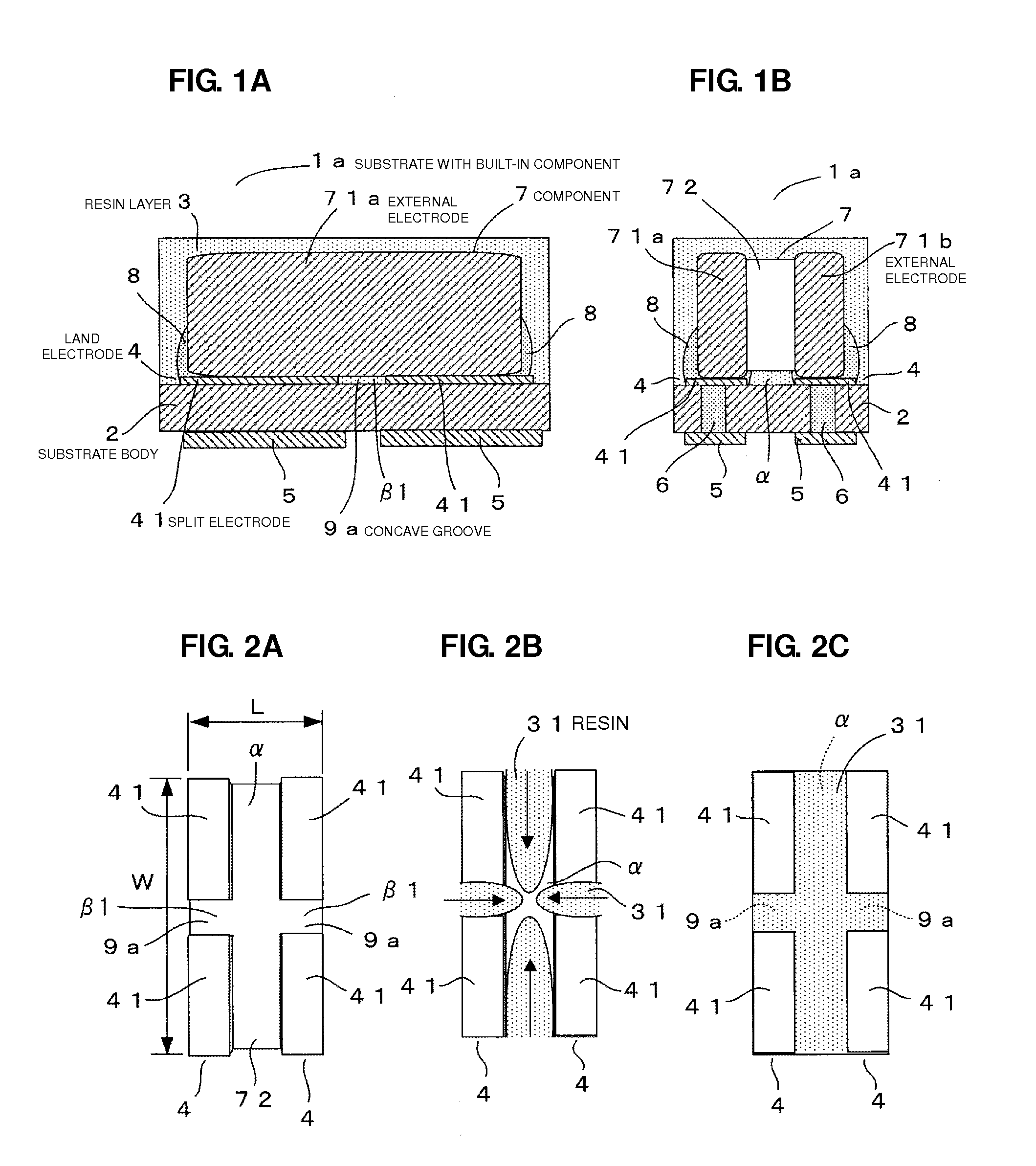
[0053]A first preferred embodiment including a core board will be described with reference to FIGS. 1A through 2C.
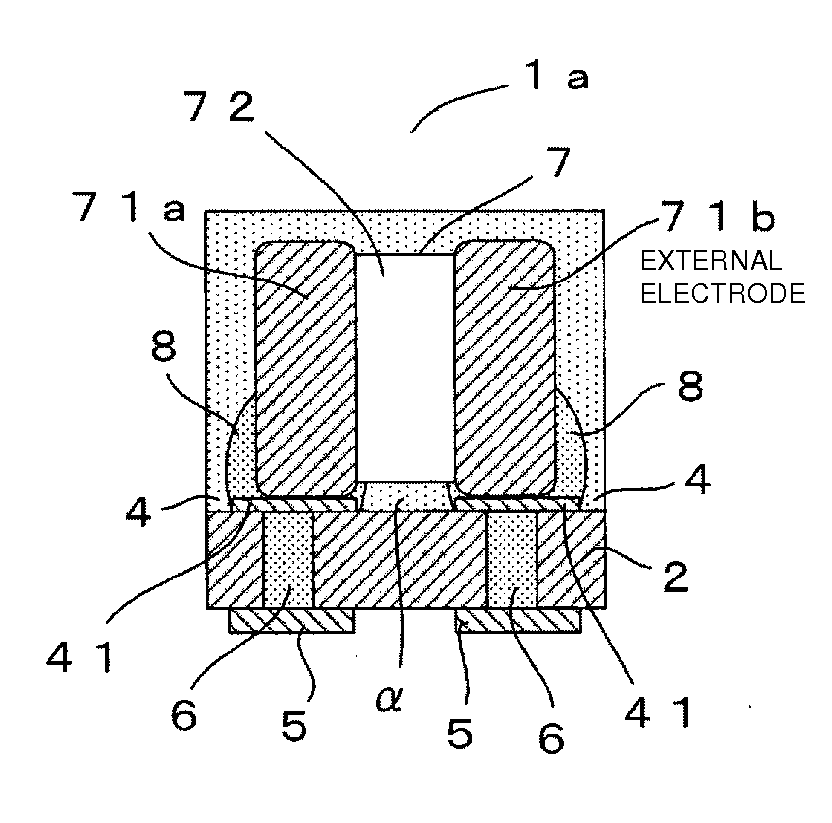
[0054]FIGS. 1A and 1B show a substrate with a built-in component 1a according to the present preferred embodiment, and the substrate with a built-in component 1a is preferably formed by laminating a resin layer 3 on a substrate body 2 to be a core board.
[0055]The substrate body 2 is a base body preferably made of a glass epoxy substrate according to an example of a multilayer / single layer wiring board, for example, and a land electrode 4 to be a component mounting electrode according to a preferred embodiment of the present invention is formed on an upper surface by printing or the like, a lower electrode 5 is formed on a lower surface by the printing or the like, and the land electrode 4 and the lower electrode 5 are connected to each other through a through-type via conductor 6 in the substrate body 2, for example.
[0056]A component 7 is mounted on an upper surface side...
second preferred embodiment
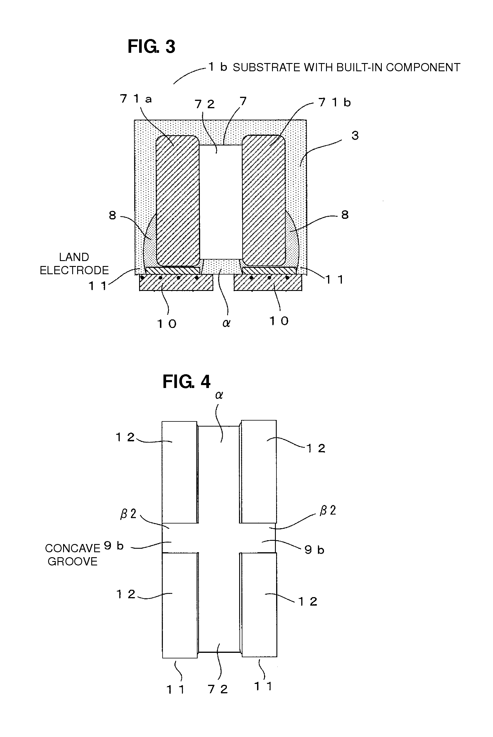
[0066]A second preferred embodiment of the coreless substrate structure including no substrate body 2 will be described with reference to FIGS. 3 to 5E.
[0067]FIG. 3 shows a substrate with a built-in component 1b according to the present preferred embodiment. In FIG. 3, the same reference numerals in FIGS. 1A, 1B and 2A-2C indicate the same or corresponding portions. In the substrate with a built-in component 1b, a metal plate 10 is provided as a base body on a lower side of external electrodes 71a and 71b of a component 7. The metal plate 10 is preferably made of a copper foil treated in a state of poor wettability such that a solder is expanded with wetting over a surface by a surface treatment with difficulty. A land electrode 11 to be a component mounting electrode according to a preferred embodiment of the present invention is preferably formed by copper plating over the metal plate 10, for example. Then, the external electrodes 71a and 71b of the component 7 are bonded to the l...
third preferred embodiment
[0077]Next, a third preferred embodiment to be a variant of the first and second preferred embodiments will be described with reference to FIG. 6.
[0078]In the present preferred embodiment, the concave groove according to the present invention is not defined by the clearances β1 and β2 provided between the split electrodes as in the first and second preferred embodiments but is preferably defined by a dent obtained by carrying out half etching or the like over the component mounting electrode according to a preferred embodiment of the present invention.
[0079]FIG. 6 is a sectional view showing the case in which the land electrode 4 according to the first preferred embodiment is applied. In the land electrode 4, a dent γ is formed by the half etching or the like in a central portion and a concave groove 9c is defined by the dent γ.
[0080]Also in the case in which the concave groove 9c is thus formed, it is possible to obtain the same advantageous effects as those in the first and second...
PUM
 Abstract
Description
Claims
Application Information