
Power converter permitted to be reduced in size and manufactured at decreased cost

a technology of power converters and power converters, which is applied in the direction of electrical equipment, electrical equipment contruction details, circuit arrangements on support structures, etc., can solve the problems of increasing the amount of metal materials used in the making of connecting components b>99/b>, reducing the production cost and weight of the power converter, and ensuring the stability of installation. , the effect of increasing the degree of vibration resistan

Active Publication Date: 2013-03-07
DENSO CORP
View PDF4 Cites 35 Cited by
  • Summary
  • Abstract
  • Description
  • Claims
  • Application Information

AI Technical Summary

Benefits of technology

The patent aims to create a power converter that is easy to make, cheaper and smaller.

Problems solved by technology

The input terminal tables 912 are disposed away from the capacitor 94 in the Z-direction, thus resulting in need for increasing the length of the connecting members 99 in the Z-direction, which leads to increase in amount of metal material used in making the connecting members 99 and in production cost of the power converter 9.
This results in decreases in production cost and weight of the power converter.

Method used


Image

  • Power converter permitted to be reduced in size and manufactured at decreased cost
  • Power converter permitted to be reduced in size and manufactured at decreased cost
  • Power converter permitted to be reduced in size and manufactured at decreased cost

Examples


first embodiment

[0069]Other arrangements and operations are identical with those in the

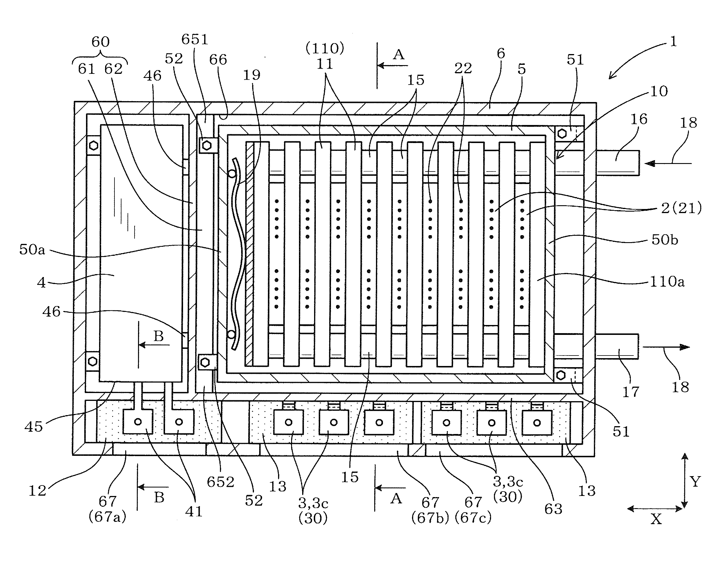
[0070]FIG. 10 illustrates the power converter 1 of the third embodiment which is different in configuration of the input terminals 41 of the capacitor 4 from that of the first embodiment. The same reference numbers, as employed in the first embodiment, refer to the same parts, and explanation thereof in detail will be omitted here.

[0071]The capacitor 4 has two input terminals 41: a first input terminal 41a and a second input terminal 41b. The first input terminal 41a is located away from the end 45 of the capacitor 4 in the Z-direction.

[0072]The second input terminal 41b is held on a terminal table 12 through a claw retainer(s) not shown which is formed on the terminal table 12. The first input terminal 41 a and the second input terminal 41b are joined together by a fastening mechanism 415 (i.e., a bolt and a nut in this embodiment).

[0073]The second input terminal 41b is formed by a first section 411, a second se...

third embodiment

[0074]The above structure of the power converter 1 of the third embodiment is so designed that the first input terminal 41 a of the capacitor 4 is located away from the end 45 of the capacitor 4, thus resulting in an increase in degree of freedom of designing the capacitor 4. The length of the second input terminal 41b (i.e., the second section 412) in the Z-direction is preferably minimized. For example, the second section 412 is so shaped as to extend at right angles from the first section 411. This results in a minimum amount of metallic material of the second input terminal 41b, thus decreasing the production cost thereof and minimizing the electric resistance that is a factor in producing the heat in the second input terminal 41b.


PUM


Abstract

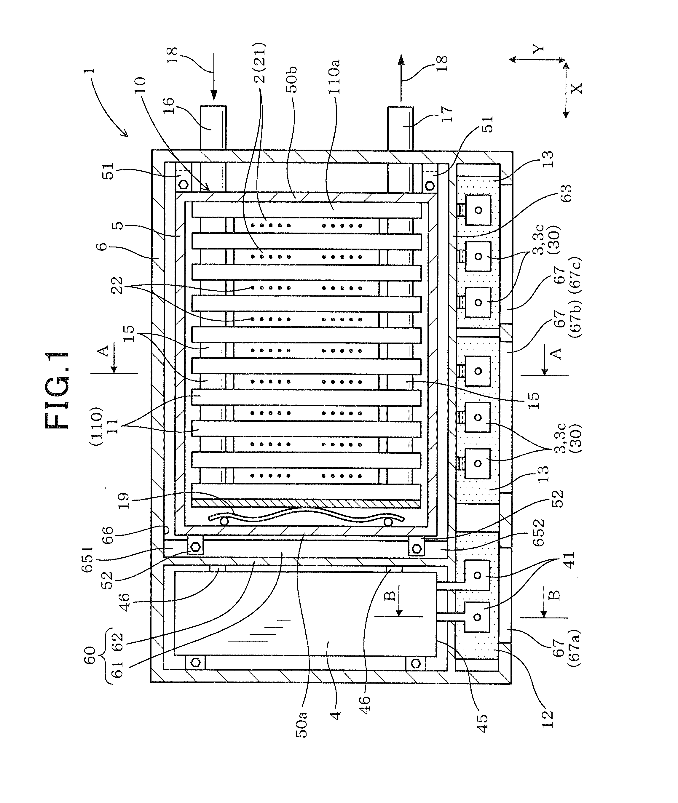
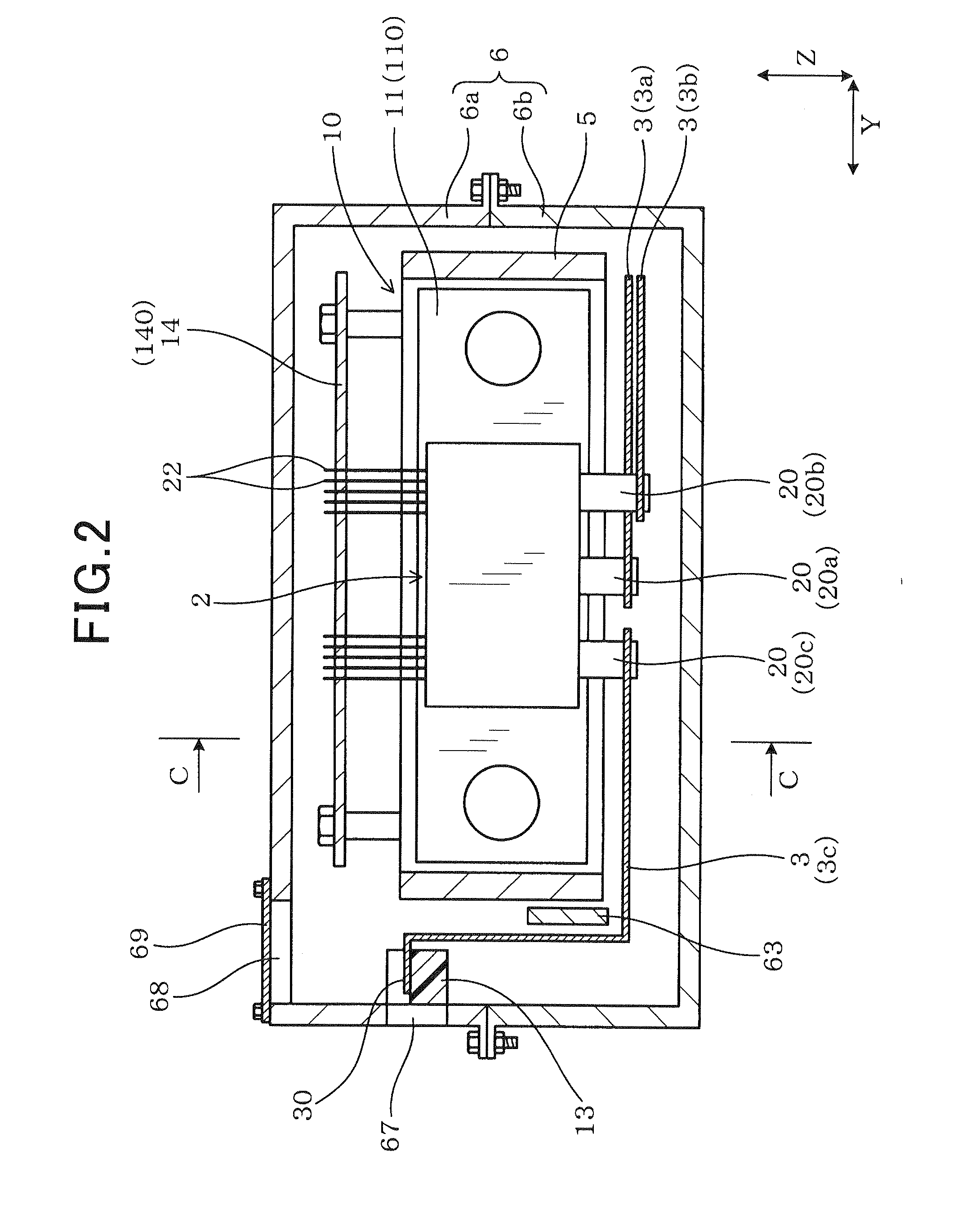
A power converter equipped with a semiconductor stack made up of semiconductor modules, bus bars coupled to power terminals of the semiconductor modules, a capacitor, and an input terminal table. The capacitor is disposed in alignment with a first direction in which the semiconductor modules are stacked. The capacitor has a first end and a second end opposed to the first end in a second direction in which the power terminals extend from the semiconductor modules. The first end faces in the second direction. The input terminal table is located near the second end of the capacitor. This structure permits the power converter to be reduced in size and produced at a decreased cost.

Description

CROSS REFERENCE TO RELATED DOCUMENT[0001]The present application claims the benefit of priority of Japanese Patent Application No. 2011-193677 filed on Sep. 6, 2011, the disclosure of which is incorporated herein by reference.BACKGROUND[0002]1. Technical Field[0003]This application relates generally to a power converter equipped with a semiconductor module in which semiconductor devices are fabricated and a capacitor working to smooth the voltage applied to the semiconductor module.[0004]2. Background Art[0005]FIGS. 11 to 13 illustrates a conventional power converter 9, as taught in Japanese Patent First Publication No. 2009-5462, which works to perform power conversion between DC power and AC power. The power converter 9 consists of a plurality of semiconductor modules 92 in which semiconductor devices are installed. Each of the semiconductor modules 92 includes power terminals 920. The semiconductor modules 92 and cooling pipes 98 for cooling the semiconductor modules 92 are laid ...

Claims


Application Information

Patent Timeline
Patent Type & Authority Applications(United States)
IPC IPC(8): H05K7/02
CPCH05K7/20927
Inventor FUNATSU, WATARU
Owner DENSO CORP
Learn More