Network control apparatus and method with port security controls

a network control and port security technology, applied in fault response, data switching networks, instruments, etc., can solve the problems of increasing processing difficulty, l2 domains cannot scale to large sizes, and retaining tenant isolation greatly complicating mobility

Active Publication Date: 2013-03-07
NICIRA
View PDF3 Cites 65 Cited by
  • Summary
  • Abstract
  • Description
  • Claims
  • Application Information

AI Technical Summary

Benefits of technology

[0005]Some embodiments of the invention provide a system that allows several different logical data path sets to be specified for several different users through one or more shared network infrastructure switching elements (referred to as “switching elements” below). In some embodiments, the system includes a set of software tools that allows the system to accept logical data path sets from users and to configure the switching elements to implement these logical data path sets. These software tools allow the system to virtualize control of the shared switching elements and the network that is defined by the connections between these shared switching elements, in a manner that prevents the different users from viewing or controlling each other's logical data path sets (i.e., each other's switching logic) while sharing the same switching elements.

Problems solved by technology

This process is of increased difficulty where the network switching elements are shared across multiple users.
Three of the many challenges of large networks (including datacenters and the enterprise) are scalability, mobility, and multi-tenancy and often the approaches taken to address one hamper the other.
For instance, one can easily provide network mobility for virtual machines (VMs) within an L2 domain, but L2 domains cannot scale to large sizes.
Also, retaining tenant isolation greatly complicates mobility.
Despite the high-level interest in SDN, no existing products have been able to satisfy all of these requirements.

Method used


Image

  • Network control apparatus and method with port security controls
  • Network control apparatus and method with port security controls
  • Network control apparatus and method with port security controls

Examples


Embodiment Construction

[0083]In the following detailed description of the invention, numerous details, examples, and embodiments of the invention are set forth and described. However, it will be clear and apparent to one skilled in the art that the invention is not limited to the embodiments set forth and that the invention may be practiced without some of the specific details and examples discussed.

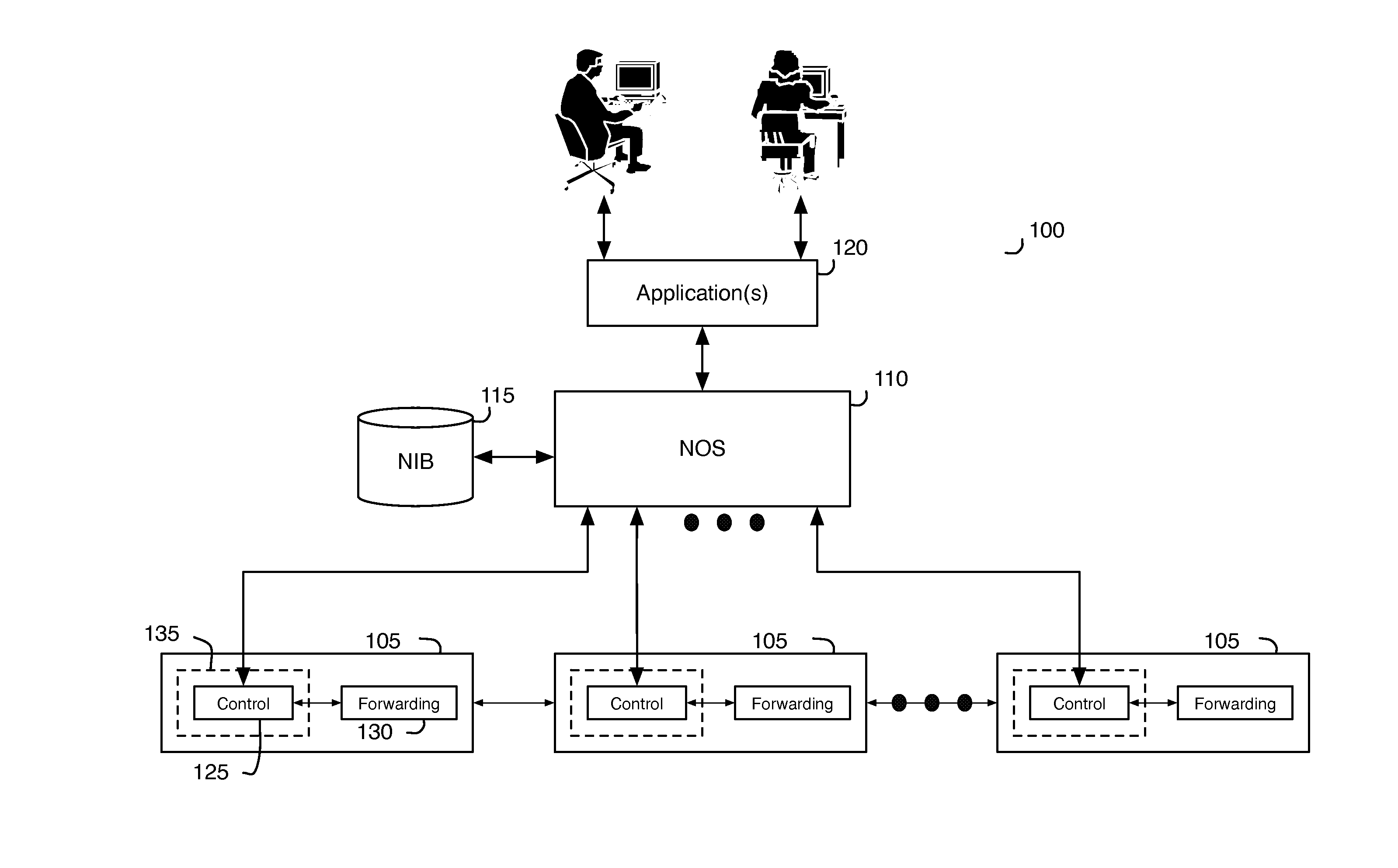
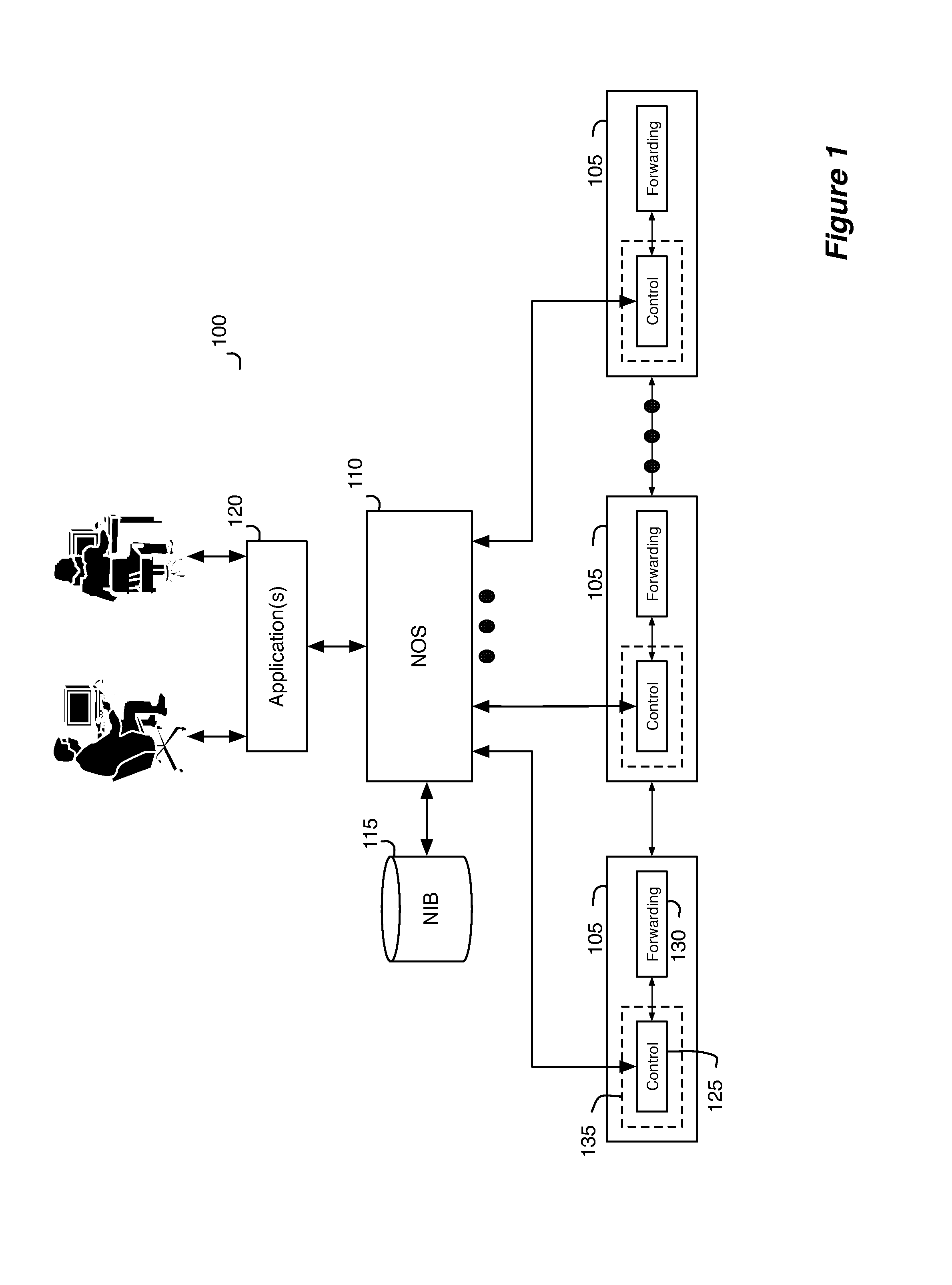
[0084]Some embodiments of the invention provide a method that allows several different logical data path sets to be specified for several different users through one or more shared switching elements without allowing the different users to control or even view each other's switching logic. In some embodiments, the method provides a set of software tools that allows the system to accept logical data path sets from users and to configure the switching elements to implement these logical data path sets. These software tools allow the method to virtualize control of the shared switching elements and the network th...


PUM


Abstract

Port security in some embodiments is a technique to apply to a particular port of a logical switching element such that the network data entering and existing the logical switching element through the particular logical port have certain addresses that the switching element has restricted the logical port to use. For instance, a logical switching element may restrict a particular logical port to one or more certain network addresses. To enable a logical port of a logical switch for port security, the control application of some embodiments receives user inputs that designate a particular logical port and a logical switch to which the particular logical port belongs. The control application in some embodiments formats the user inputs into logical control plane data specifying the designation. The control application in some embodiments then converts the logical control plane data into logical forwarding data that specify port security functions.

Description

CLAIM OF BENEFIT TO PRIOR APPLICATIONS[0001]This application claims benefit to U.S. Provisional Patent Application 61 / 361,912, filed on Jul. 6, 2010; U.S. Provisional Patent Application 61 / 361,913, filed on Jul. 6, 2010; U.S. Provisional Patent Application 61 / 429,753, filed on Jan. 4, 2011; U.S. Provisional Patent Application 61 / 429,754, filed on Jan. 4, 2011; U.S. Provisional Patent Application 61 / 466,453, filed on Mar. 22, 2011; U.S. Provisional Patent Application 61 / 482,205, filed on May 3, 2011; U.S. Provisional Patent Application 61 / 482,615, filed on May 4, 2011; U.S. Provisional Patent Application 61 / 482,616, filed on May 4, 2011; U.S. Provisional Patent Application 61 / 501,743, filed on Jun. 27, 2011; and U.S. Provisional Patent Application 61 / 501,785, filed on Jun. 28, 2011. These provisional applications are incorporated herein by reference.BACKGROUND[0002]Many current enterprises have large and sophisticated networks comprising switches, hubs, routers, servers, workstations...

Claims


Application Information

Patent Timeline
Patent Type & Authority Applications(United States)
IPC IPC(8): H04L12/56H04L45/586H04L49/111
CPCH04L41/0896H04L49/70G06F11/07H04L49/1546H04L12/5689H04L12/5696H04L41/0893H04L49/3063G06F15/17312H04L45/586H04L49/00H04L41/0895H04L41/122H04L41/0894H04L45/036H04L45/76H04L12/4633H04L47/783H04L45/00H04L61/5007H04L2101/622H04L45/02H04L41/0816H04L41/0853
Inventor FULTON, BRYAN J.THAKKAR, PANKAJKOPONEN, TEEMUBALLAND, III, PETER J.
Owner NICIRA
Why Eureka
Try Eureka