Fault diagnosis device for temperature sensor

a temperature sensor and fault diagnosis technology, applied in the direction of machines/engines, electrical control, instruments, etc., can solve the problem of affecting the efficiency of achieve the effect of efficient fault diagnosis of temperature sensors

Active Publication Date: 2013-03-07
NISSAN MOTOR CO LTD
View PDF0 Cites 19 Cited by
  • Summary
  • Abstract
  • Description
  • Claims
  • Application Information

AI Technical Summary

Benefits of technology

[0009]With the present invention, even if the predetermined amount of time has not elapsed since the internal combustion engine was stopped, the fault diagnosis of the temperature sensor to be subjected to fault diagnosis can be executed when each portion of the internal combustion engine reach the thermal equilibrium state. As a result, the fault diagnosis of the temperature sensor can be executed efficiently.

Problems solved by technology

However, with the technology of Japanese Laid-Open Patent Application No. 2004-339969, since the timing at which the temperature sensor fault diagnosis is executed occurs after the engine has been stopped for a predetermined amount of time corresponding to when the temperatures near each of the radiator-side cooling water temperature sensor, the engine-side cooling water temperature sensor, and the intake air temperature sensor should be substantially equal to the outside ambient temperature, it is not possible to execute a fault diagnosis of the temperature sensors when the engine is started before the predetermined amount of time has elapsed and the fault diagnosis of the temperature sensors will tend to be delayed.

Method used


Image

  • Fault diagnosis device for temperature sensor
  • Fault diagnosis device for temperature sensor
  • Fault diagnosis device for temperature sensor

Examples


Embodiment Construction

[0016]An embodiment of the present invention will now be explained based on the drawings.

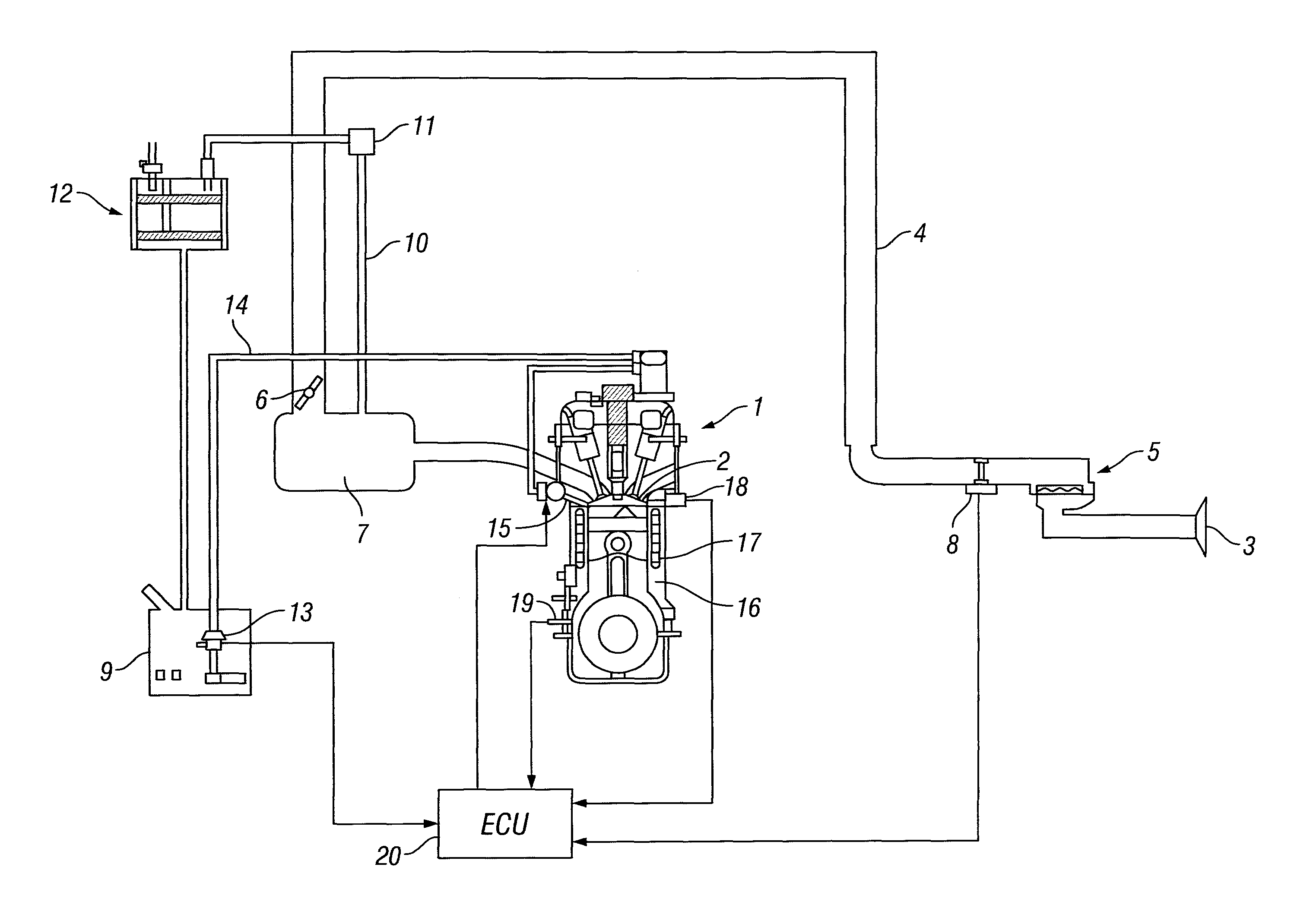
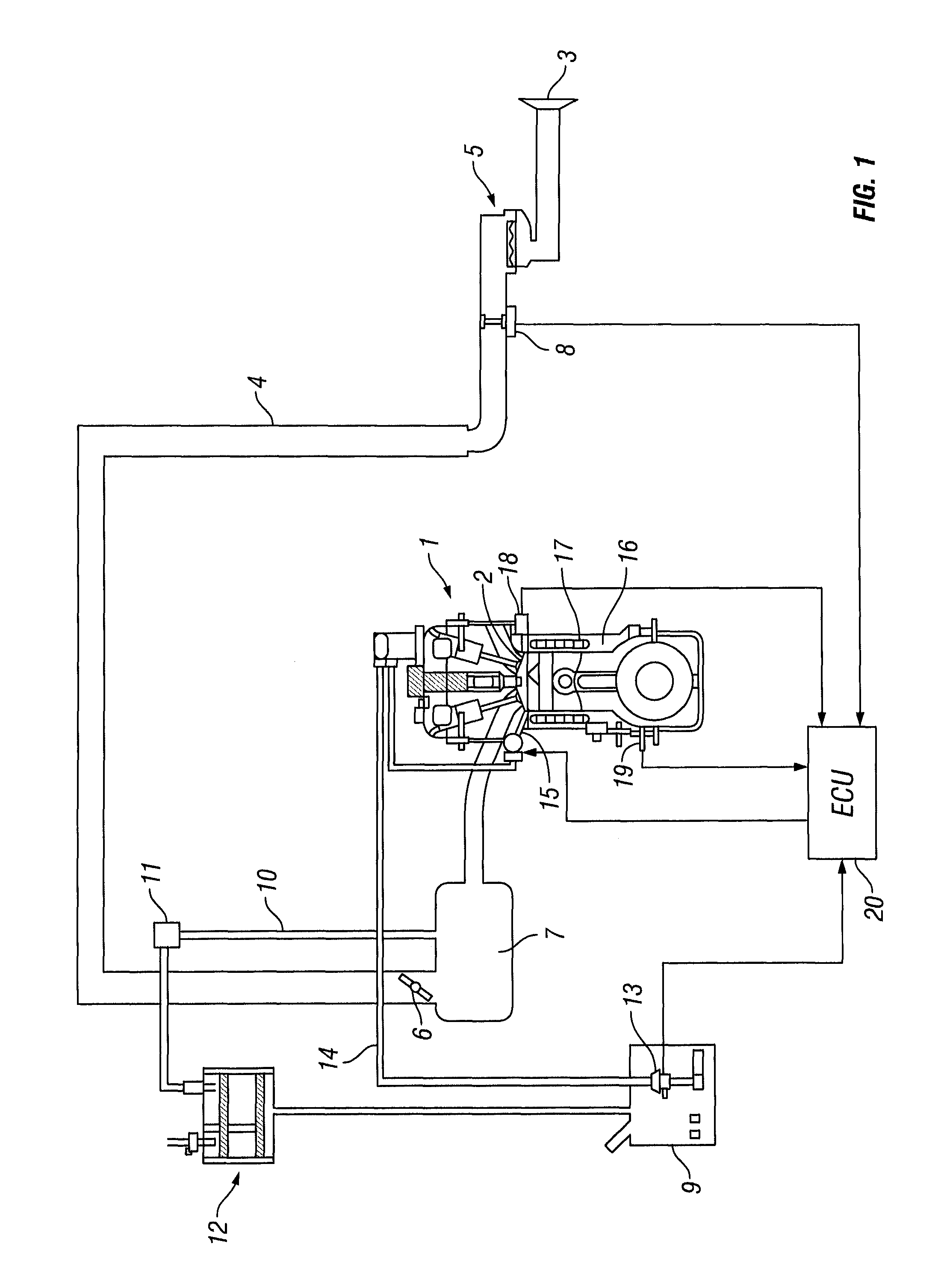
[0017]FIG. 1 is a simple diagram illustrating constituent features of an internal combustion engine system in which the present invention is employed.

[0018]Air is drawn in through an intake air port 3 that is open to the atmosphere and guided through an intake air passage 4 to a combustion chamber 2 of an internal combustion engine 1 installed in a vehicle.

[0019]An air filter 5, a throttle valve 6, and a collector 7 are provided in the intake air passage 4 in order as listed from upstream to downstream.

[0020]An intake air temperature sensor 8 is provided between the air cleaner 5 and the throttle valve 6. The intake air temperature sensor 8 is provided inside an air flow meter.

[0021]A purge passage 10 is connected to the intake air passage 4 at a position downstream of the throttle valve 6 and serves to introduce fuel vapor generated in a fuel tank 9. A purge control valve 11 is installed in the...


PUM

PropertyMeasurementUnit
voltageaaaaaaaaaa
temperatureaaaaaaaaaa

Abstract

A fault diagnosis device conducts a fault diagnosis in a temperature sensor. At starting an internal combustion engine, a thermal equilibrium condition may be established and temperature deviations of temperatures detected by at least two reference temperature sensors from each other may be equal to or less than a predetermined value, with the temperatures detected by the reference temperature sensors being greatly deviated from one detected by a temperature sensor being diagnosed. In this case, if the temperatures detected by the reference temperature sensors do not drop by a predetermined temperature or more from starting the engine until a predetermined time elapses, the fault diagnosis device determines that the temperature sensor being diagnosed is faulty.

Description

CROSS-REFERENCE TO RELATED APPLICATIONS[0001]This application is a U.S. National stage application of International Application No. PCT / JP2011 / 061405, filed May 18, 2011, which claims priority claims priority under to Japanese Patent Application No. 2010-117939, filed in Japan on May 24, 2010, the entire contents of which is hereby incorporated by reference.BACKGROUND OF THE INVENTION[0002]1. Field of the Invention[0003]The present invention generally relates to a fault diagnosis device that executes a fault diagnosis of at least three sensors each configured to detect a temperature of a different measurement entity.[0004]2. Background Information[0005]A known technology for executing a fault diagnosis of a temperature sensor uses detection values of several reference temperature sensors that are different from the temperature sensor being subjected to fault diagnosis.[0006]Japanese Laid-Open Patent Application No. 2004-339969, for example, discloses a technology that includes a rad...

Claims


Application Information

Patent Timeline
Patent Type & Authority Applications(United States)
IPC IPC(8): G01N25/72
CPCF02D41/042Y02T10/40F02D41/222F02D41/1446F02D41/061F02D2200/021F02D2200/023F02D2200/0414F02D2200/0606
Inventor SAKURADA, YAMATO
Owner NISSAN MOTOR CO LTD
Why Eureka
Try Eureka