Bidirectional controllable overrunning clutch and control method thereof

An overrunning clutch, controllable technology, applied in the direction of one-way clutches, clutches, mechanical equipment, etc., can solve problems such as inability to quickly diagnose faults, difficult product modification and maintenance, and large axial space requirements, and achieve processing technology Mature, reduced development and use costs, easy to deploy

Pending Publication Date: 2019-06-14
JILIN BOCHENG DRIVETRAIN TECH CO LTD
View PDF2 Cites 5 Cited by
  • Summary
  • Abstract
  • Description
  • Claims
  • Application Information

AI Technical Summary

Problems solved by technology

The clutch described in this invention has a large number of parts, requires a large axial space, is difficult to arrange, and has a high degree of coupling between various parts, making it difficult to carry out product modification and maintenance
In addition, the clutch described in this invention is not equipped with a sensor to detect the position of the actuator. Once a fault occurs, it cannot quickly diagnose the fault and make effective treatment, and the reliability of the system is low.

Method used


Image

  • Bidirectional controllable overrunning clutch and control method thereof
  • Bidirectional controllable overrunning clutch and control method thereof
  • Bidirectional controllable overrunning clutch and control method thereof

Examples


Embodiment 1

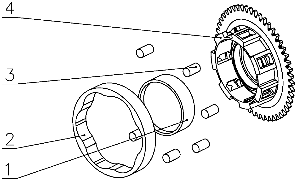
[0055] This embodiment discloses a two-way controllable overrunning clutch, which is composed of a cage drive assembly, a roller actuator assembly and a control assembly.

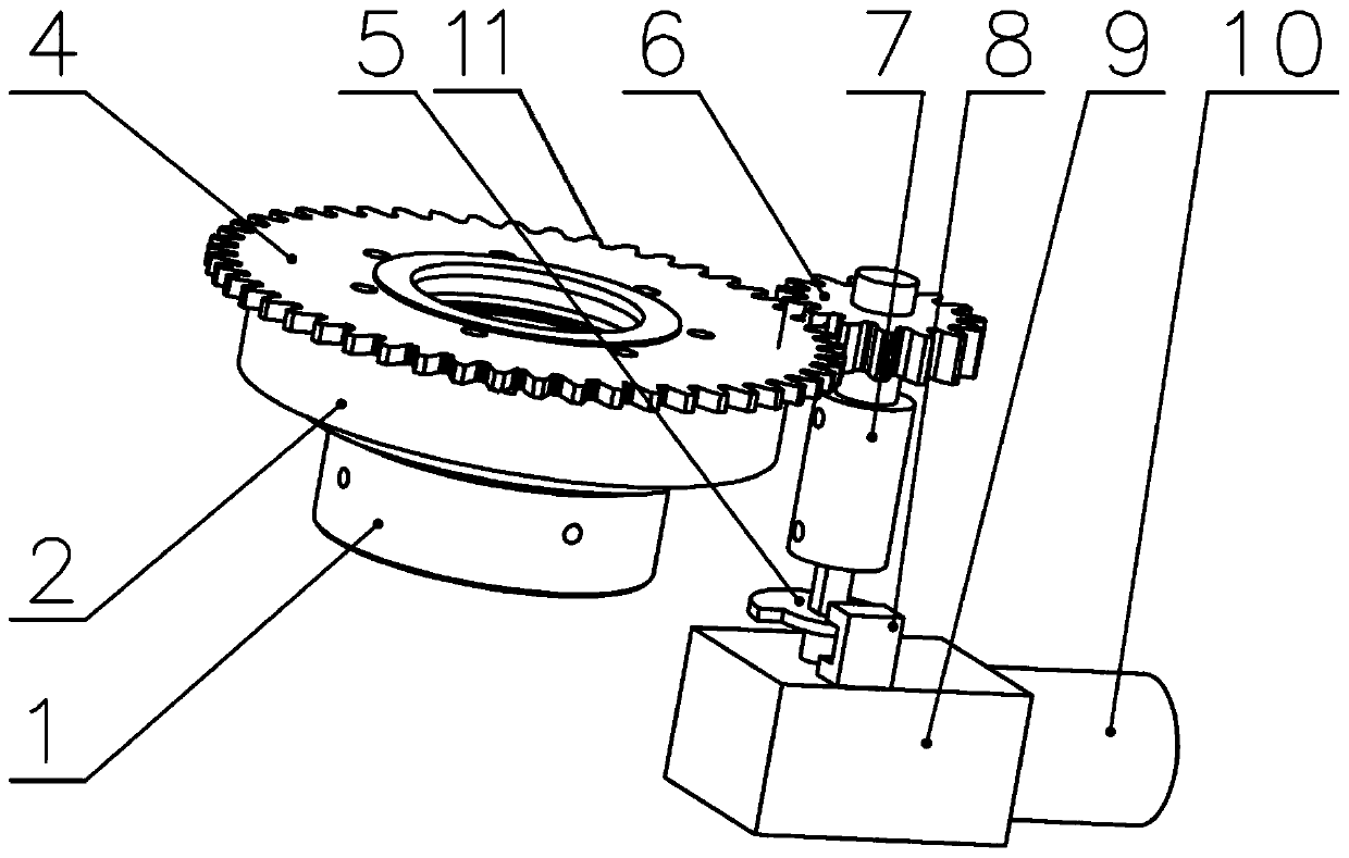
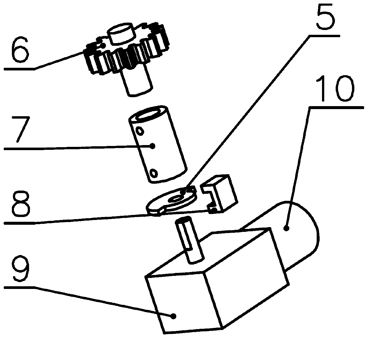
[0056] like figure 1 and figure 2 As shown, the cage driving assembly is composed of a driving motor 10 , a worm gear reducer 9 , a flexible coupling 7 , a driving gear 6 and a driven gear 11 . Wherein, the drive motor 10 is used as the power source of the cage drive assembly to output the rotational driving force outwards, and the output shaft of its power output end is coaxially fixedly connected with the input shaft of the worm gear box 9, and the worm gear box 9 The output shaft is coaxially connected with the gear shaft of the driving gear 6 through a flexible coupling 7, and the worm gear reducer 9 is fixed on the gearbox housing. The driving gear 6 meshes with the driven gear fixed on the end face of the cage 4 .

[0057] In the cage drive assembly, the drive motor 10 provides energy through the ...

Embodiment 2

[0070] This embodiment discloses a two-way controllable overrunning clutch, which is composed of a cage drive assembly, a roller actuator assembly and a control assembly.

[0071] like Figure 4 and Figure 5 As shown, the cage driving assembly is composed of a push-pull electromagnet 15 , a rigid coupling 14 , a connecting rod 13 , a pin 12 and a bar-shaped groove plate 16 . Wherein, the push-pull electromagnet 15 is used as the power source of the cage drive assembly to output a linear push-pull driving force outwards, and the push-pull rod at the output end of the push-pull electromagnet 15 is rigidly connected with one end of the connecting rod 13 through a rigid coupling 14, so The push-pull electromagnet 15 is fixed on the gearbox housing, the other end of the connecting rod 13 is provided with a counterbore, and the pin 12 is fixedly installed in the counterbore at the end of the connecting rod 13 through interference fit, The strip grooved plate 16 is fixedly mounted...


PUM


Abstract

The invention provides a bidirectional controllable overrunning clutch. The bidirectional controllable overrunning clutch consists of a retainer driving assembly, a roller executing assembly and a control assembly, wherein the control terminal of the retainer driving assembly is coaxially and fixedly connected with a retainer of the roller executing assembly; in the roller executing assembly, a plurality of fusiform spaces are formed between the outer wall of an inner ring and the inner wall of an outer ring, wherein two ends of each fusiform space are narrow, and the middle part of each fusiform space is wide; a plurality of toggling frames are arranged perpendicular to the end surface of the retainer, in the circumferential direction of the retainer; the retainer is arranged between theinner ring and the outer ring in a sleeving manner; the toggling frames of the retainer are in one-to-one correspondence with the fusiform spaces; rollers are correspondingly mounted in the toggling frames of the retainer; under the driving of the rotating of the retainer, each roller moves in a circumferential direction in the corresponding fusiform space between the corresponding inner ring andthe corresponding outer ring; and the control assembly is in control connection with the retainer driving assembly to control the retainer driving assembly to drive the retainer to rotate in an axialdirection. The bidirectional controllable overrunning clutch disclosed by the invention is stable and reliable in performance, simple and compact in structure and good in control performance.

Description

technical field [0001] The invention belongs to the technical field of clutches and control thereof in mechanical automatic transmissions, and in particular relates to a two-way controllable overrunning clutch and a control method thereof. Background technique [0002] With the gradual maturity of the pure electric vehicle market, the market puts forward higher requirements for its comfort, power and economy. In order to meet the diversified use requirements, multi-gear electric vehicle drive system is an important development trend of pure electric vehicles today. [0003] Mechanical automatic transmissions are developed on the basis of manual transmissions. Mechanical automatic transmission retains the advantages of traditional manual transmission, such as high transmission efficiency, low cost and convenient operation, and has been widely used. [0004] Aiming at the performance characteristics of pure electric vehicles, the Chinese patent: A non-power interruption shif...

Claims


Application Information

Patent Timeline
Patent Type & Authority Applications(China)
IPC IPC(8): F16D41/10F16D41/064
Inventor 尹倪岳汉奇蔡文奇韩毓东楚汉昆高炳钊
Owner JILIN BOCHENG DRIVETRAIN TECH CO LTD
Why Eureka
Try Eureka