Nuclear reactor power monitor

a technology for monitoring nuclear reactors and power, applied in nuclear engineering, nuclear elements, greenhouse gas reduction, etc., can solve the problems of large oscillation, deterioration of cooling characteristics of fuel rod surface temperature, and distribution and liquidity of neutron fluxes, so as to enhance monitoring accuracy and reliability

Inactive Publication Date: 2013-03-07
KK TOSHIBA
View PDF4 Cites 12 Cited by
  • Summary
  • Abstract
  • Description
  • Claims
  • Application Information

AI Technical Summary

Benefits of technology

[0022]The present invention has been made in order to solve the above-mentioned problems and it is an object of the present invention to provide a technology for enhancing the monitoring accuracy and reliability in nuclear thermal hydraulic stability of a nuclear reactor.

Problems solved by technology

However, it is known that depending on the core flow and other operating conditions, neutron flux distribution and liquidity in the reactor core are destabilized by delayed transportation of voids and a negative feedback effect caused by negative void reactivity coefficients in the reactor core.
There is concern that occurrence of such a nuclear thermal hydraulic destabilization phenomenon may result in considerable oscillation of output power and flow rate, which may deteriorate cooling characteristics in terms of fuel rod surface temperature and may damage the soundness of fuel rod cladding tubes.
In such a range where deterioration in nuclear thermal hydraulic stability is expected, limited operation is preset for safety.

Method used


Image

  • Nuclear reactor power monitor
  • Nuclear reactor power monitor
  • Nuclear reactor power monitor

Examples


first embodiment

[0061]The embodiments of the present invention will be described hereinbelow with reference to the accompanying drawings.

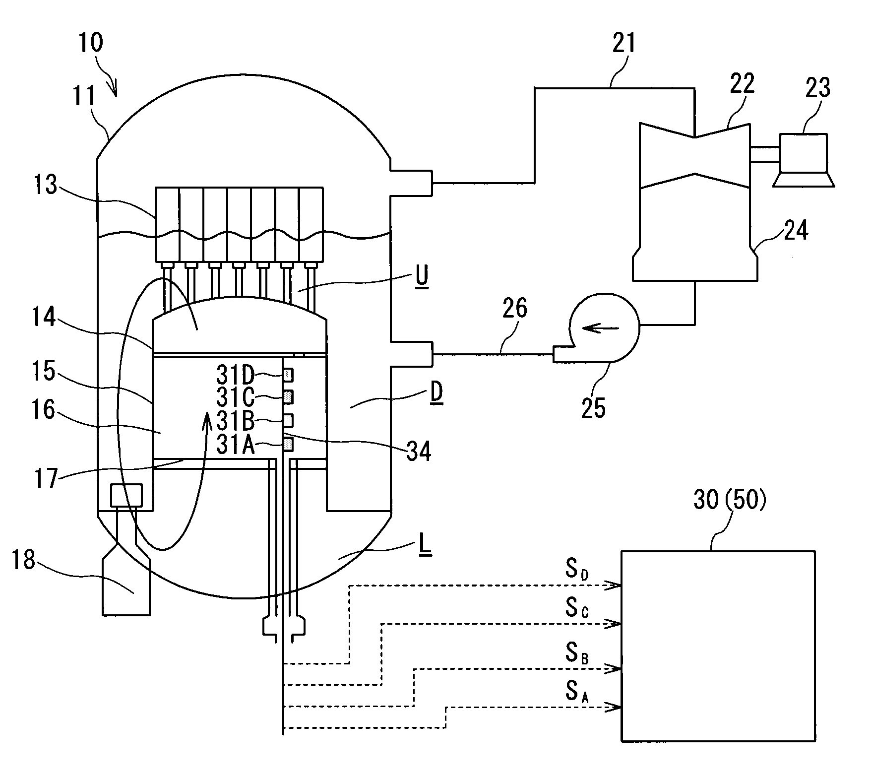
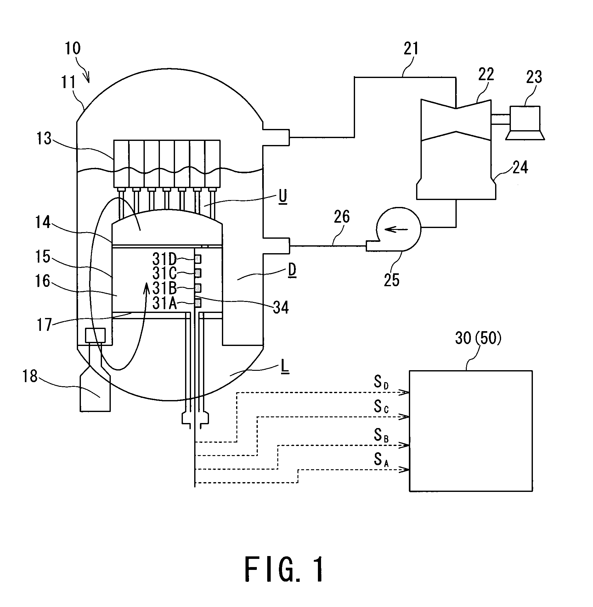
[0062]A nuclear power generation system shown in FIG. 1 includes: a nuclear reactor 10 which heats furnace water by the heat generated through nuclear fission of nuclear fuel and thereby generates steam; a main line 21 which guides the generated steam to a turbine 22; a generator 23 coaxially connected with the turbine 22 which is rotationally driven by the steam to convert rotational kinetic energy to electric energy; a condenser 24 which cools and condenses the steam, which was expanded in the process of doing its work in the turbine 22, into condensate water; and a water supply line 26 which sends the condensate water to the nuclear reactor 10 with a pump 25.

[0063]Feed water returned to the nuclear reactor 10 is reheated as furnace water, and the above-stated process is repeated to perform continuous power generation. To sustain the power generation in a stable...

second embodiment

[0265]As shown in FIG. 27, a power monitor 50 includes: a first calculation unit 52 configured to calculate a decay ratio γ as a first stability index based on time series data t indicating power oscillation in nuclear instrumentation signals S outputted from a plurality of nuclear instrumentation detectors 31 which detect neutrons in a reactor core 16; a first determination unit 53 configured to compare the first stability index (decay ratio γ) and a first reference value D and determine whether nuclear thermal hydraulic stability of the reactor core 16 is stable or deteriorated; a second calculation unit 54 configured to calculate a second stability index R of the reactor core 16 by counting the time series data determined to indicate deterioration in the first determination unit 53; and a second determination unit 55 configured to compare the second stability index R and a second reference value P and determine whether to perform suppressing operation of the power oscillation.

[02...

third embodiment

[0309]With reference to FIG. 33, a nuclear reactor power monitor according to a third embodiment will be explained. In FIG. 33, component members identical or corresponding to those in FIG. 27 are designated by identical reference signs, and foregoing descriptions are used therefor to omit detailed explanation.

[0310]A power monitor 50 of the third embodiment is different from the power monitor of the second embodiment in that the activation instruction unit 56 instructs activation of the power suppression device 80 when a second stability index Rk exceeds the second reference value P at least in two or more groups.

[0311]The power monitor 50 of the third embodiment is further different from the power monitor of the second embodiment in that a reference value correction unit 71 is included.

[0312]A graph of FIG. 34 represents decay ratios of nuclear instrumentation signals SA to SD outputted from the nuclear instrumentation detectors 31A to 31D (FIG. 1) placed at positions different in...


PUM


Abstract

Provide a nuclear reactor power monitoring technology for enhancing the monitoring accuracy and reliability in nuclear thermal hydraulic stability.
A power monitor 30 includes a first calculation unit 42,52 configured to calculate a first stability index based on time series data indicating power oscillation in nuclear instrumentation signals outputted from a plurality of nuclear instrumentation detectors 31; a first determination unit 44,53 configured to compare the first stability index and a first reference value and determine whether nuclear thermal hydraulic stability of the reactor core is stable or deteriorated; a second calculation unit 46,54 configured to calculate a second stability index of the reactor core based on the time series data when the deteriorated state is determined in the first determination unit 44,53; and a second determination unit 47,55 configured to compare the second stability index and a second reference value and determine whether to perform suppressing operation of the power oscillation.

Description

TECHNICAL FIELD[0001]The present invention relates to a technology for monitoring nuclear reactor power during operation.BACKGROUND ART[0002]In the boiling water reactor (BWR), output power can be controlled by changing a core flow and thereby changing a steam ratio (void fraction) inside a boiling reactor core.[0003]However, it is known that depending on the core flow and other operating conditions, neutron flux distribution and liquidity in the reactor core are destabilized by delayed transportation of voids and a negative feedback effect caused by negative void reactivity coefficients in the reactor core.[0004]There is concern that occurrence of such a nuclear thermal hydraulic destabilization phenomenon may result in considerable oscillation of output power and flow rate, which may deteriorate cooling characteristics in terms of fuel rod surface temperature and may damage the soundness of fuel rod cladding tubes.[0005]Accordingly, in designing fuels and reactor cores for the boi...

Claims


Application Information

Patent Timeline
Patent Type & Authority Applications(United States)
IPC IPC(8): G21C7/00
CPCG21C17/00G21C17/10Y02E30/40G21D2003/005G21D3/001G21D3/005Y02E30/00Y02E30/30
Inventor TAKEUCHI, YUTAKAONO, HIROSHIYANO, KAZUKI
Owner KK TOSHIBA
Why Eureka
Try Eureka