Over-The-Air Test

a test and over-the-air technology, applied in the field of over-the-air testing, can solve the problems of interference with the radio connection, fading of different durations and strengths of received signals, and the testing system becomes more complicated and expensive, and achieves accurate angular power distribution.

Active Publication Date: 2013-03-07
KEYSIGHT TECH SINGAPORE (SALES) PTE LTD
View PDF3 Cites 28 Cited by
  • Summary
  • Abstract
  • Description
  • Claims
  • Application Information

AI Technical Summary

Benefits of technology

[0011]The invention provides an accurate angular power distribution with a low number of antenna-element-specific channels and antenna elements.

Problems solved by technology

When a radio frequency signal is transmitted from a transmitter to a receiver, the signal propagates in a radio channel along one or more paths having different angles of arrivals, signal delays, polarizations and powers, which cause fadings of different durations and strengths in the received signal.
In addition, noise and interference due to other transmitters interfere with the radio connection.
However, when the number of antenna-element-specific channels increases, the testing system becomes more complicated and expensive.

Method used


Image

  • Over-The-Air Test
  • Over-The-Air Test
  • Over-The-Air Test

Examples


Embodiment Construction

[0027]Exemplary embodiments of the present invention will now be described more fully hereinafter with reference to the accompanying drawings, in which some, but not all embodiments of the invention are shown. Indeed, the invention may be embodied in many different forms and should not be construed as limited to the embodiments set forth herein; rather, these embodiments are provided so that this disclosure will satisfy applicable legal requirements. Although the specification may refer to “an”, “one”, or “some” embodiment(s) in several locations, this does not necessarily mean that each such reference is to the same embodiment(s), or that the feature only applies to a single embodiment. Single features of different embodiments may also be combined to provide other embodiments. Therefore, all words and expressions should be interpreted broadly and they are intended to illustrate, not to restrict, each embodiment.

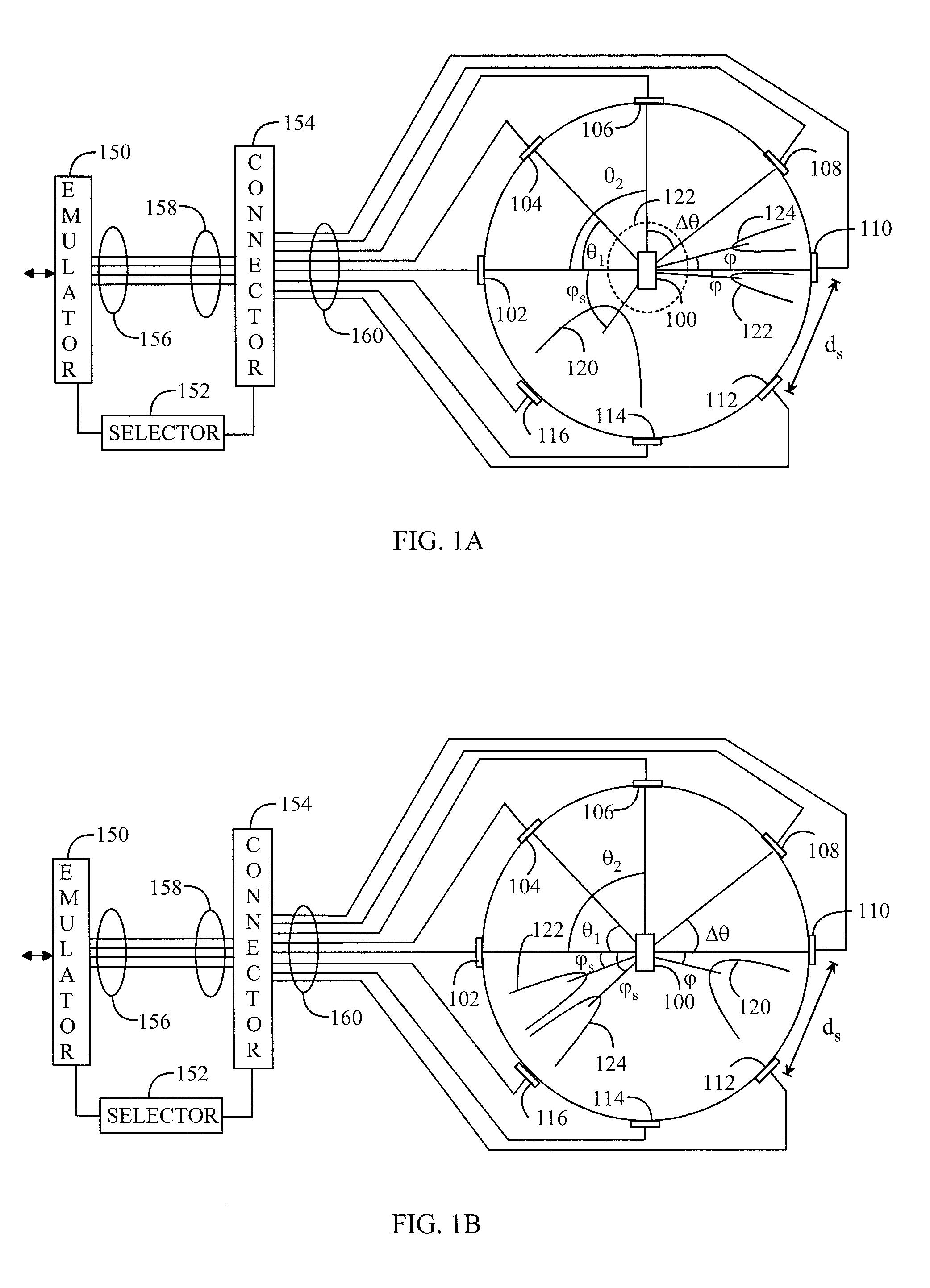
[0028]FIGS. 1A and 1B present a plane geometrical embodiment of an OTA ...


PUM


Abstract

An emulating system of an over-the-air test comprises a radio channel emulator, a selector, a connector and a plurality of antenna elements placed around a test spot for an electronic device under test. The selector receives data on a simulated radio channel from the radio channel emulator and selects a subset of a plurality of positions of antenna elements on the basis of the data. The connector connects only the antenna elements in the subset and the radio channel emulator for physically realizing the simulated radio channel.

Description

CROSS-REFERENCE TO RELATED APPLICATION[0001]This application is a National Stage application of International Application No. PCT / FI2010 / 050419, filed May 24, 2010, which is incorporated by reference herein in its entirety.FIELD [0002]The invention relates to an over-the-air testing of a device in an anechoic chamber.DESCRIPTION OF THE RELATED ART[0003]When a radio frequency signal is transmitted from a transmitter to a receiver, the signal propagates in a radio channel along one or more paths having different angles of arrivals, signal delays, polarizations and powers, which cause fadings of different durations and strengths in the received signal. In addition, noise and interference due to other transmitters interfere with the radio connection.[0004]A transmitter and a receiver can be tested using a radio channel emulator emulating real circumstances. In a digital radio channel emulator, a radio channel is usually modeled with an FIR filter (Finite Impulse Response). A traditional...

Claims


Application Information

Patent Timeline
Patent Type & Authority Applications(United States)
IPC IPC(8): H04B17/00
CPCH01Q21/20H04B7/0691H04B7/0874G01R29/105H01Q3/24H04B17/0087H04B17/391G01R29/08H01Q21/06H04B17/00
Inventor KYOSTI, PEKKANUUTINEN, JUKKA-PEKKAMALM, JUHAMATTI
Owner KEYSIGHT TECH SINGAPORE (SALES) PTE LTD
Why Eureka
Try Eureka