Dual purpose touch sensor panel and optical retarder

a touch sensor and optical retarder technology, applied in the field of touch sensor panels, can solve the problems of reducing the visibility of the image displayed on the lcd, light reflecting off the device can create glare, so as to reduce the visibility of the image, reduce reducing the effect of glar

Active Publication Date: 2013-03-14
APPLE INC
View PDF3 Cites 21 Cited by
  • Summary
  • Abstract
  • Description
  • Claims
  • Application Information

AI Technical Summary

Benefits of technology

[0004]When a user operates a touch sensor panel having an LCD device outdoors or in a bright environment, light reflecting off the device can create glare. In order to reduce this glare, a user can view the device through polarized filters. These polarized filters can be, for example, polarized sunglasses. Doing so, however, can reduce...

Problems solved by technology

When a user operates a touch sensor panel having an LCD device outdoors or in a bright environment, light reflecting off the device can create glare.
When a user operates a touch sensor panel having an LCD device outdoors or in a bright environment, light r...

Method used


Image

  • Dual purpose touch sensor panel and optical retarder
  • Dual purpose touch sensor panel and optical retarder
  • Dual purpose touch sensor panel and optical retarder

Examples


Embodiment Construction

[0028]In the following description of preferred embodiments, reference is made to the accompanying drawings which form a part hereof, and in which it is shown by way of illustration specific embodiments that can be practiced. It is to be understood that other embodiments can be used and structural changes can be made without departing from the scope of the embodiments of this disclosure.

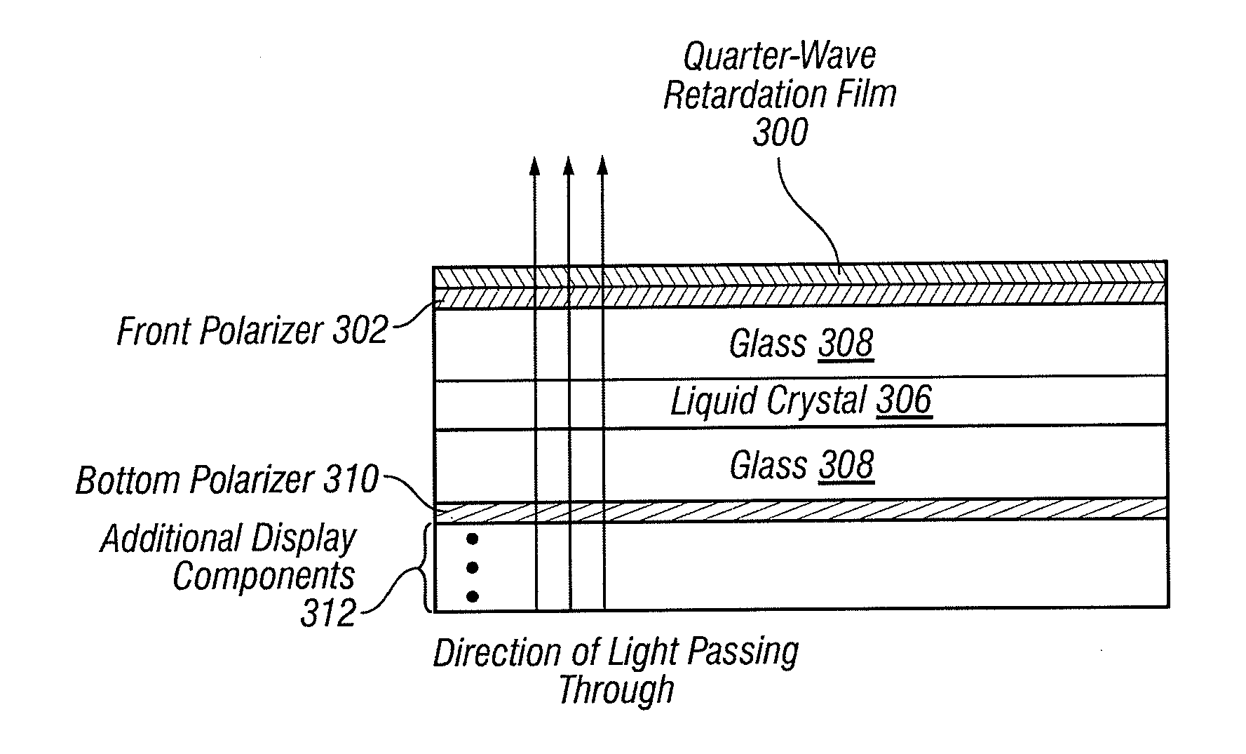
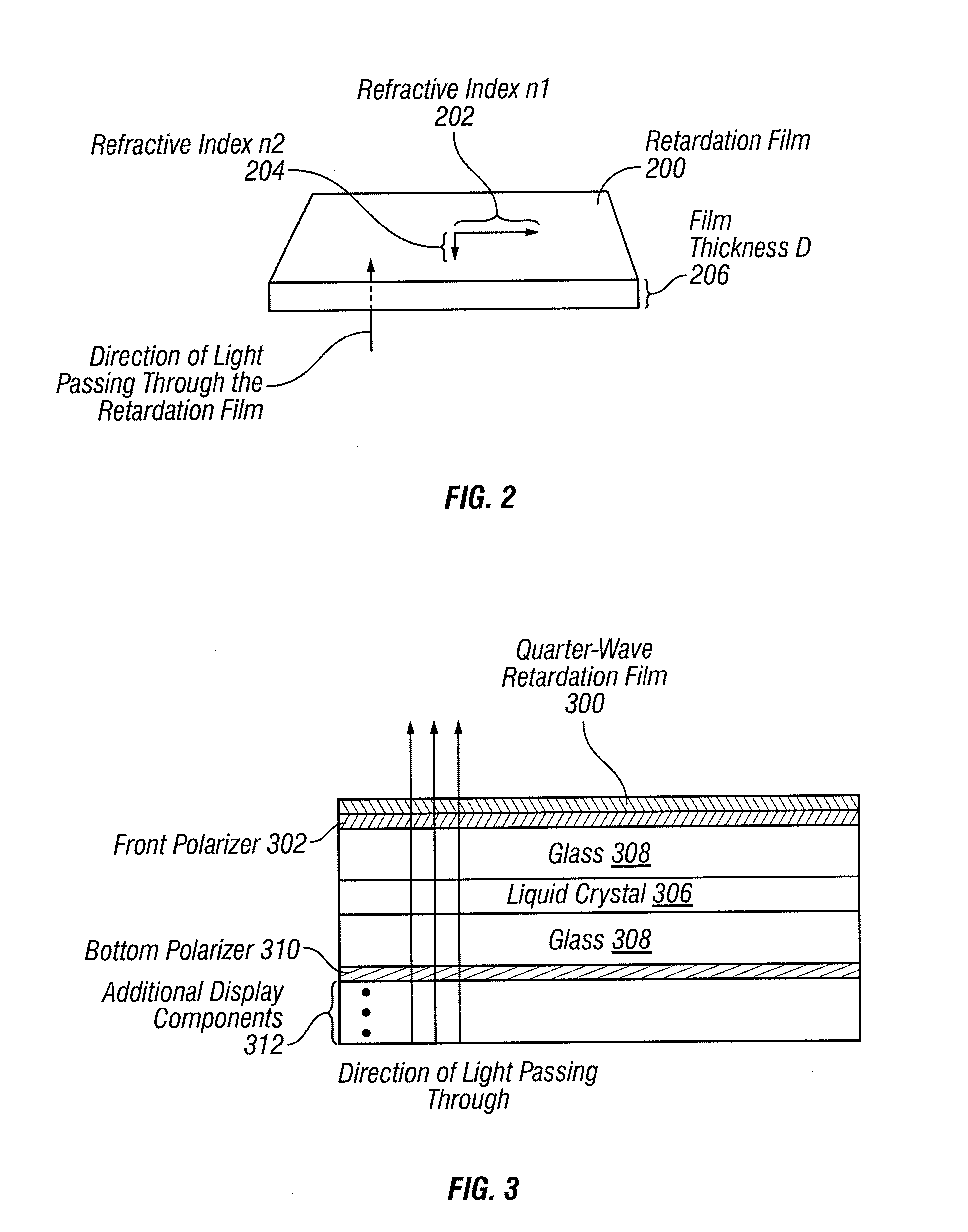
[0029]Embodiments of the disclosure relate to a touch sensor panel having an LCD or other device that displays an image that can be viewed through polarized filters at various angles without a significant reduction in display image quality. These polarized filters can be, for example, polarized sunglasses. LCD devices can emit linearly polarized light. When used outdoors or in a bright environment, a device housing the touch sensor panel and LCD device can reflect light and create glare. Although a user can wear polarized sunglasses to reduce the effects of glare, the visibility of the image displaye...


PUM


Abstract

When a user operates a touch sensor panel having an LCD device outdoors or in a bright environment, light reflecting off the device can create glare. In order to reduce glare, a user can view the device through polarized filters such as polarized sunglasses.
Doing so can reduce the visibility of the image displayed on the LCD. A quarter-wave retardation film can be added to the touch sensor panel's LCD device to mitigate these effects by producing circularly polarized light. However, adding a separate quarter-wave retardation film can increase the thickness and cost of manufacturing the touch sensor panel. Embodiments of the present disclosure are directed to a touch sensor panel constructed from a base film having quarter-wave retardation properties that can produce circularly polarized light. Because the base film has the desired optical properties, a separate quarter-wave retardation film may not be needed.

Description

FIELD OF THE DISCLOSURE[0001]This relates generally to a touch sensor panel and, more particularly, to the construction of a touch sensor panel display that can be viewed by a user wearing linearly polarized filters such as polarized sunglasses.BACKGROUND OF THE DISCLOSURE[0002]Display screens of various types of technologies, such as liquid crystal displays (LCDs), organic light emitting diode (OLED) displays, etc., can be used as screens or displays for a wide variety of electronic devices, including such consumer electronics as televisions, computers, and handheld devices (e.g., cellular telephones, audio and video players, gaming systems, and so forth). LCD devices, for example, typically provide a flat display in a relatively thin package that is suitable for use in a variety of electronic goods including touch sensor panels. LCD technology is based on polarization optics and typically employs a linear polarizer on the front surface that emits linearly polarized light. Linearly...

Claims


Application Information

Patent Timeline
IPC IPC(8): G02F1/1335H01L51/50H01J9/24G02B5/30
CPCG02F1/13338G06F3/044G06F3/042G02F2001/133638G02F2001/133635G06F3/0443G02F1/133635G02F1/133638G02F1/1333G06F3/0412G02F1/13363G02F1/133634H04N9/3105H04N9/3197
Inventor CHEN, CHENGMOHAPATRA, SIDDHARTHHUANG, LILIZHONG, JOHN Z.KUWABARA, MASATO
Owner APPLE INC
Why Eureka
Try Eureka