Bulb-type LED lamp having replaceable light source module

a technology of light source module and led lamp, which is applied in the field of lamps, can solve the problems of long life and hard damage, waste of user's usable components, and easy burnout or breakage of led or the circuit board of the light source module, so as to increase the practicability and convenience of the lamp, and reduce the waste of usable components. , the effect of saving maintenance costs

Inactive Publication Date: 2013-03-14
CHAUN CHOUNG TECH
View PDF3 Cites 61 Cited by
  • Summary
  • Abstract
  • Description
  • Claims
  • Application Information

AI Technical Summary

Benefits of technology

[0007]The present invention is to provide a bulb-type LED lamp having a replaceable light source module, whereby the light source module can be replaced by a new one rapidly and the maintenance cost is reduced to conform to the requirements for environmental protection.
[0016]According to the present invention, since the light source module is detachably and electrically connected to the lamp head module in such a manner that the sleeve is disposed into the lamp casing module, when the LED or the circuit board of the light source module burns down, the sleeve can be detached from the lamp casing module to replace the damaged light source module with a new one. The original lamp head module and the lamp casing module of the lamp can be reused, so that the user needs not to buy another whole set of the bulb-type lamp. Therefore, the maintenance cost is saved greatly and the waste of usable components is reduced to conform to the requirements for environmental protection.
[0017]Since the light source module of the present invention can be replaced rapidly, the LEDs of different colors can be selectively used to change the color of light of the lamp, which increases the practicability and convenience of the lamp.
[0018]According to another feature of the present invention, the light source module comprises a metallic pressing plate. The upper surface of the metallic pressing plate is brought into thermal contact with the substrate arranged with the LEDs thereon. The lower surface of the metallic pressing plate tightly abuts a heat-conducting plate of the lamp casing module to form thermal contact. Further, the heat-conducting plate is brought into thermal contact with a heat-dissipating body of the lamp casing module. Thus, the heat generated by the LEDs is conducted from the substrate to the metallic pressing plate, the heat-conducting plate and the heat-dissipating body, and is finally dissipated to the outside via the heat-dissipating body. Since the thermal contact among the substrate, the metallic pressing plate and the heat-conducting plate is generated by a planar surface, the thermal contact area is sufficient, whereby the heat-conducting effect and the heat-dissipating effect are improved greatly.

Problems solved by technology

Generally speaking, the heat-dissipating casing is made of metals having high thermal conductivity, which is long in lifetime and hard to damage.
In comparison with the heat-dissipating casing, the LED or the circuit board of the light source module is prone to burn down or break down.
Hence, when the light source module breaks down, the user has to discard the damaged light source module together with the heat-dissipating casing, the lamp head and the lamp cover, which wastes a lot of usable components for the user and thus does not conform to the requirement for environmental protection.
Another problem of the conventional bulb-type LED lamp lies in that: the heat generated by the LED cannot be effectively conducted to the heat-dissipating casing because the LEDs are arranged on the circuit board and the thermal contact area between the circuit board and the heat-dissipating casing is insufficient.
As a result, the whole heat-dissipating effect is insufficient, so that the circuit board and the LED of the light source module may be burn down easily.

Method used


Image

  • Bulb-type LED lamp having replaceable light source module
  • Bulb-type LED lamp having replaceable light source module
  • Bulb-type LED lamp having replaceable light source module

Examples


Embodiment Construction

[0025]The detailed description and technical contents of the present invention will become apparent with the following detailed description accompanied with related drawings. It is noteworthy to point out that the drawings is provided for the illustration purpose only, but not intended for limiting the scope of the present invention.

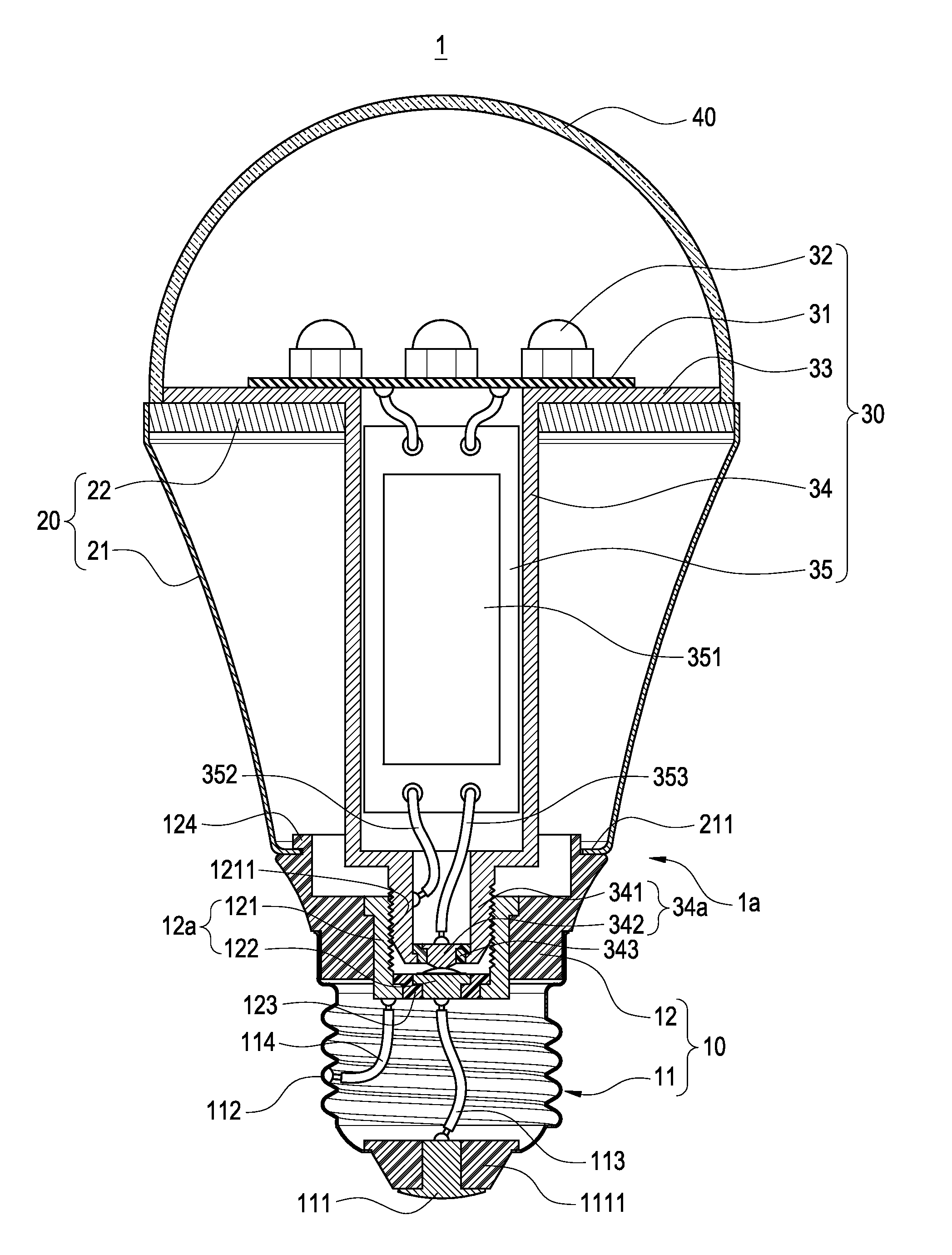
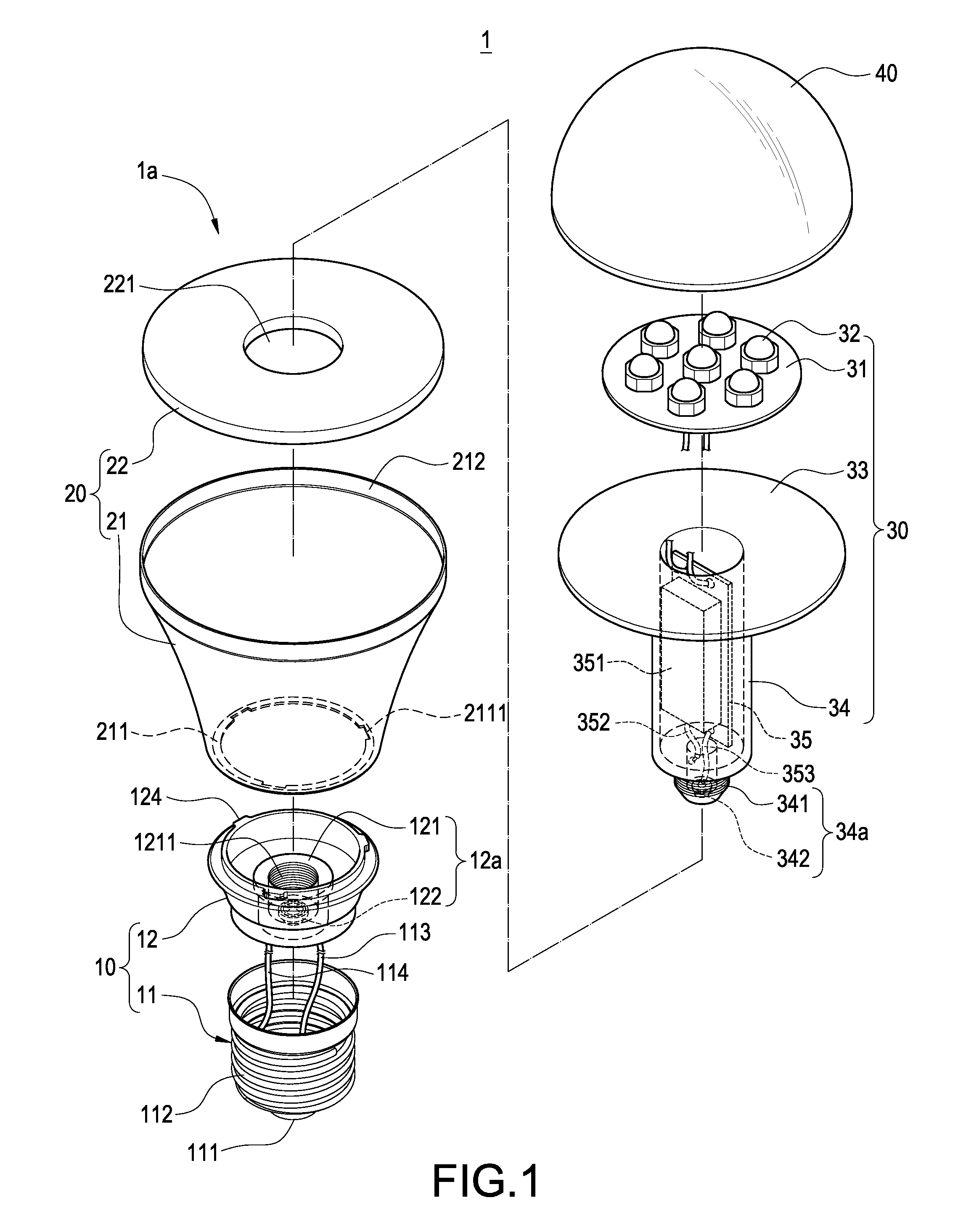
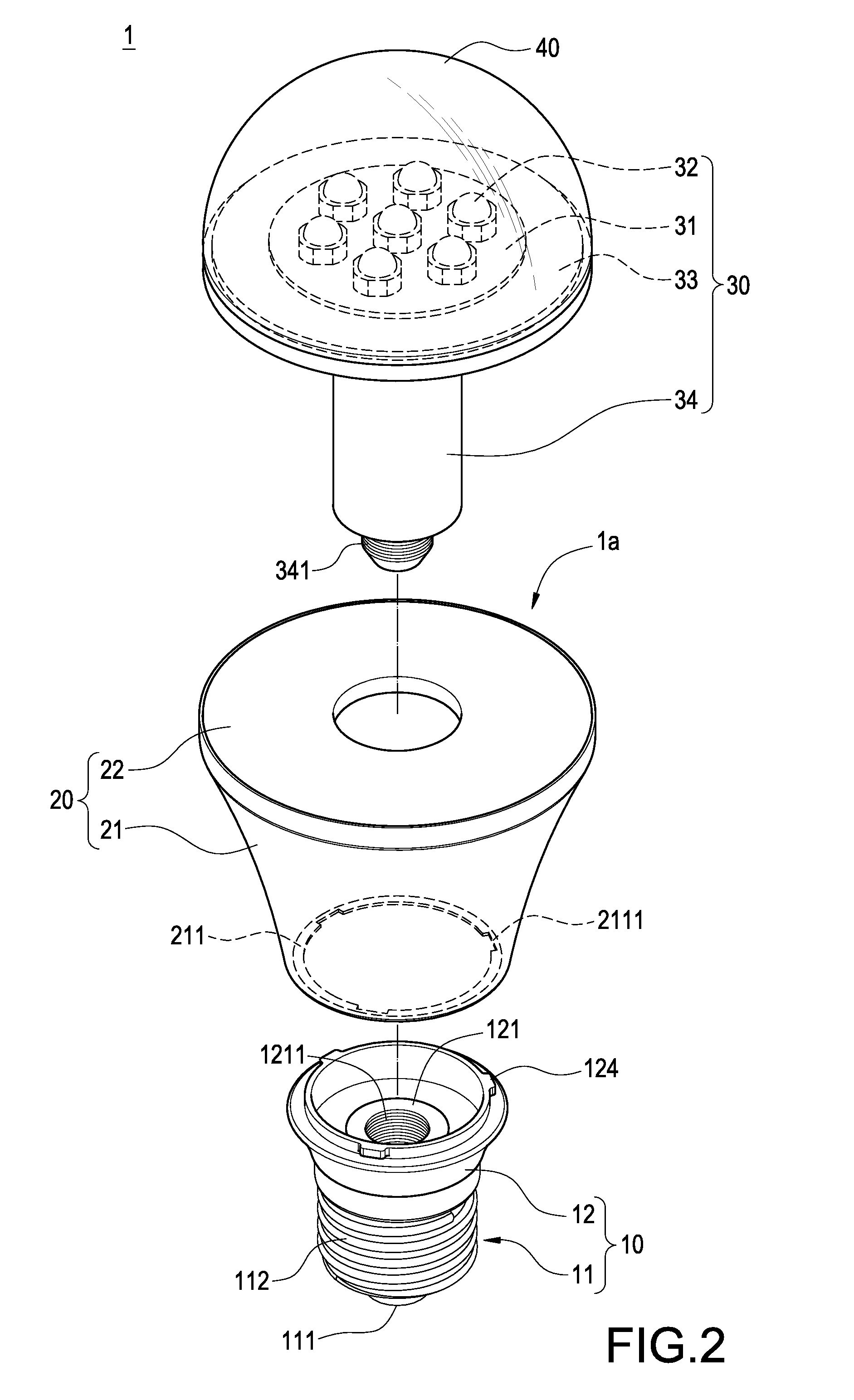
[0026]Please refer to FIGS. 1 to 4, which show the first embodiment of the present invention. The present invention provides a bulb-type lamp 1 having a replaceable light source module, which includes a lamp head module 10, a lamp casing module 20, and a light source module 30. It can be clearly seen from FIGS. 2 and 3 that, the lamp head module 10 is combined with the lamp casing module 20 to form a lamp body 1a. Then, the light source module 30 is inserted into the lamp body 1a in such a manner that the light source module 30 is disposed into the lamp casing module 20 to be assembled with the lamp head module 10. By this structure, the light source mod...


PUM


Abstract

A bulb-type LED lamp having a replaceable light source module includes a lamp head module, a lamp casing module and a light source module. The lamp head module has an electrical-conductive connection portion. One end of the lamp casing module is connected to the lamp head module. The light source module comprises a substrate, a plurality of LEDs electrically connected to the substrate, and a sleeve disposed in the lamp casing module to be electrically connected to the substrate. The sleeve has an electrical-conductive insertion portion assembled with the electrical-conductive connection portion. By this structure, a damaged light source module can be replaced rapidly. A user needs not to by a new whole set lamp so as to save the cost maintenance. Further, a surface thermal contact is generated between the metallic pressing plate and the heat-conducting plate to increase the heat-conducting area and efficiency.

Description

BACKGROUND OF THE INVENTION[0001]1. Field of the Invention[0002]The present invention relates to a lamp, and in particular to a bulb-type LED lamp having a replaceable light source module.[0003]2. Description of Prior Art[0004]With the rapid advance of science and technology, light-emitting diodes (LEDs) are widely used in lighting apparatuses to replace traditional incandescent bulb because the LEDs are low in electricity consumption, high in brightness, long in lifetime and etc. A conventional bulb-type lamp includes a lamp head, a heat-dissipating casing, a circuit board, a plurality of LED arranged on the circuit board, and a lamp cover. Generally speaking, the heat-dissipating casing is made of metals having high thermal conductivity, which is long in lifetime and hard to damage. In comparison with the heat-dissipating casing, the LED or the circuit board of the light source module is prone to burn down or break down. Hence, when the light source module breaks down, the user ha...

Claims


Application Information

Patent Timeline
Patent Type & Authority Applications(United States)
IPC IPC(8): F21S4/00
CPCF21K9/1355F21V19/045F21Y2105/001F21Y2101/02F21V3/00F21V19/04F21K9/20F21K9/232F21K9/238F21Y2105/10F21Y2115/10
Inventor WU, HUEI-JANHSU, ZU-CHAO
Owner CHAUN CHOUNG TECH
Why Eureka
Try Eureka