Fault-based unit replacement

a technology of fault-based units and replacement parts, which is applied in the field of fault-based unit replacement, can solve the problems of inability to quickly identify and correct malfunctions, inconvenience for users sharing a single multi-function device, and malfunctions that cannot be immediately remedied

Active Publication Date: 2013-03-14
XEROX CORP
View PDF20 Cites 13 Cited by
  • Summary
  • Abstract
  • Description
  • Claims
  • Application Information

AI Technical Summary

Problems solved by technology

Malfunctions in the operations of a multifunction device do, on occasion occur, leading to inconvenience for the users sharing the single multifunction device.
Because multifunction devices are appreciated for their achieving rapid delivery times for task commands, the back-up foremost causes frustrations to the persons that are unable to easily identify and correct the malfunction.
In certain instances, the malfunction may not be immediately remedied, as various internal parts must be repaired or replaced by a visiting technician, in which case costs associated with decreased productivity and lost time are incurred by the entity utilizing such a multifunction device.
Unfortunately, the identification of the part requiring replacement may not be ascertainable until such time as the service technician has physical access to the multifunction device.

Method used


Image

  • Fault-based unit replacement
  • Fault-based unit replacement
  • Fault-based unit replacement

Examples


Embodiment Construction

[0019]One or more implementations of the subject application will now be described with reference to the attached drawings, wherein like reference numerals are used to refer to like elements throughout.

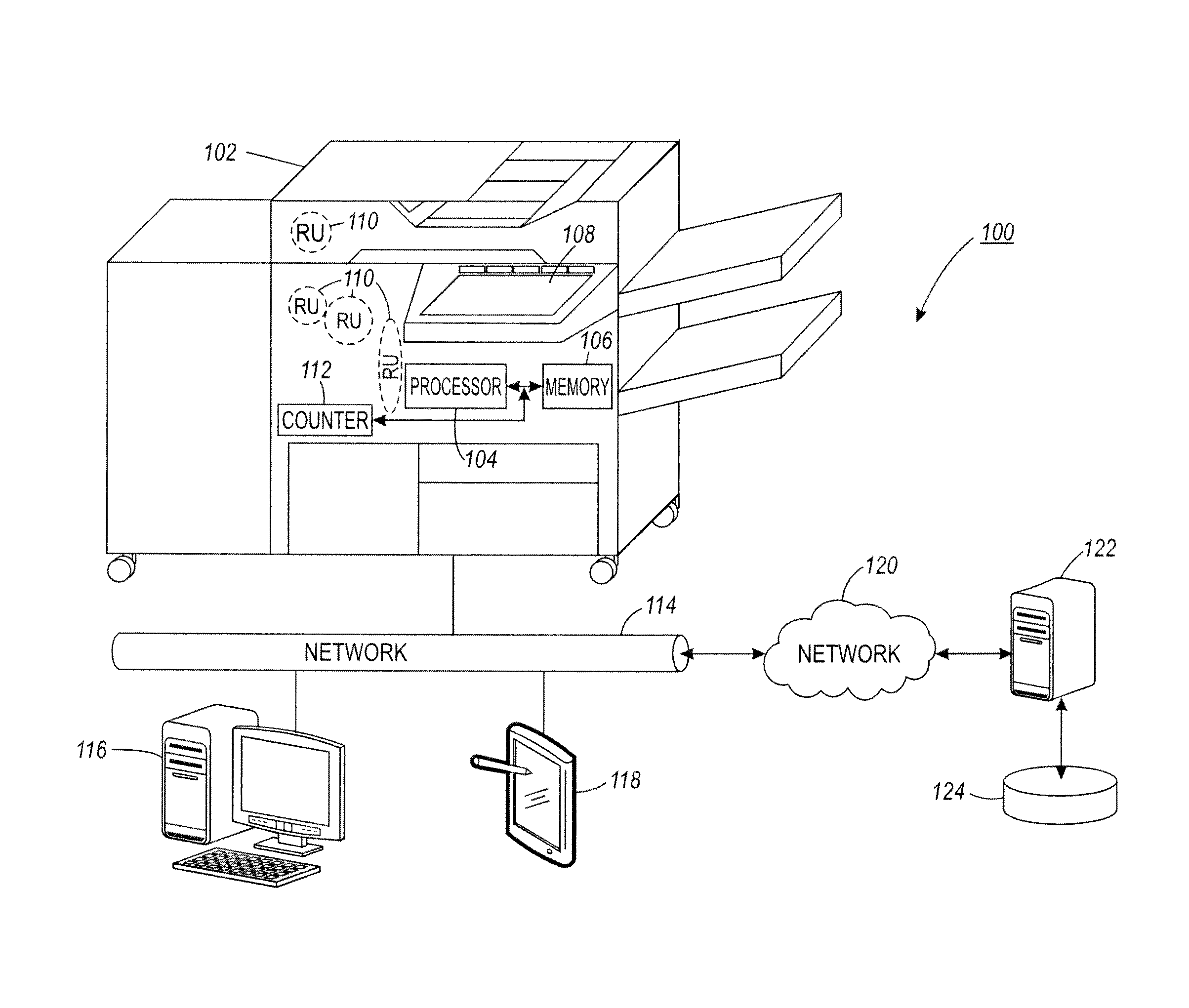
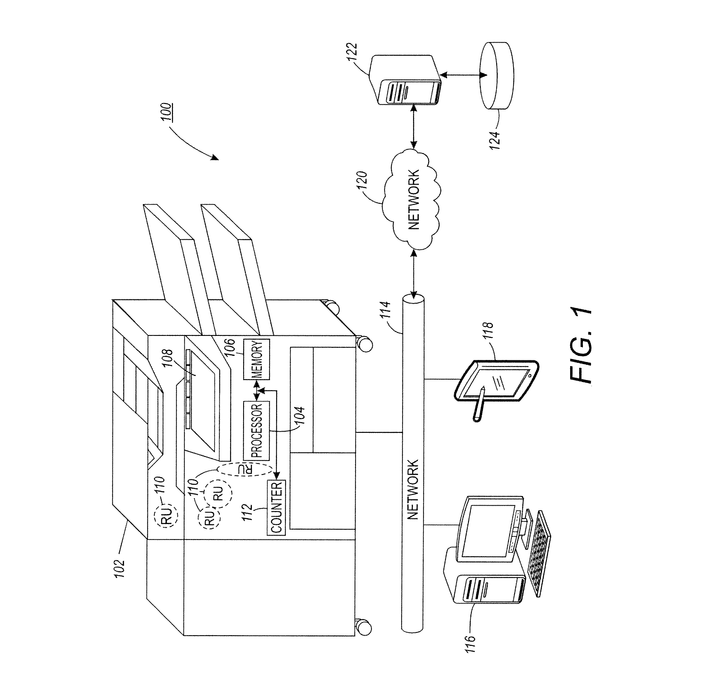
[0020]The embodiments described herein relate generally to a system and method for an accurate and reliable mechanism for use with a multifunction device which provides customers with routine capabilities to self-service the multifunction device when at least one expired or faulty replaceable unit is identified by the routine as needing replacement. Although the system finds particular application in multifunction devices, it will be appreciated that selected aspects may find application in related areas encountering issues of predicting at least one replaceable unit needing replacement.

[0021]The aforementioned replaceable units may be located within or associated with a multifunction device, and have a useful life expectancy based upon a number of operations, cycles, feeds, prints, o...


PUM


Abstract

A method and system are disclosed for determining the end of life condition for a replaceable unit, which may be associated with a multifunction device, and have a useful life expectancy based upon a number of operations. A counter associated with the multifunction device maintains a running count of operations for the unit. Once the number of performed operations of the replaceable unit reaches a given percentage of the expected life of that unit, an analysis is performed on a running history of the fault codes. Once the number of fault codes attributable to any given replaceable unit meets or exceeds a predetermined level, such as a percentage of the running history, a notification is generated indicating a need to replace the replaceable unit.

Description

TECHNICAL FIELD[0001]The presently disclosed embodiments disclosed herein are applicable to methods and systems for determining an end of life condition of a replaceable part as could be used in a number of devices such as, for example, multifunction devices.BACKGROUND[0002]A multiple-function printer copier machine, i.e., a document printer, copier, scanner, and facsimile (hereinafter “multifunction device”), can perform a number of simultaneous tasks initiated at the device itself, or via a work station and / or routed from a plurality of remote network locations. In some instances, a central multifunction device shared by at least two separate network locations has proven to be an effective asset in office environments to reduce monetary costs associated with setting up individual multifunction devices at each network location, conserve space that would otherwise be used by multiple work stations supporting individual multifunction devices, and save time associated with the individ...

Claims


Application Information

Patent Timeline
Patent Type & Authority Applications(United States)
IPC IPC(8): G06F11/00
CPCG06F11/008G07C3/02G07C3/00
Inventor GEARING, MARK JOHNABBOTT, STEPHEN JOHNMONAHAN, LEE PAUL
Owner XEROX CORP
Why Eureka
Try Eureka